
Instructions


- 5 -
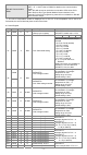
3. CR#32 communication format settings: for DVP04PT-S modules with firmware V4.14 or previous
versions, b11~b8 data format selection is not available. For ASCII mode, the format is fixed to 7, E, 1
(H’00XX) and for RTU mode, the format is fixed to 8, E, 1 (H’C0xx/H’80xx). For modules with firmware
V4.15 or later, refer to the following table for setups. Note that the original code H’C0XX/H’80XX will be
seen as RTU, 8, E, 1 for modules with firmware V4.15 or later.
b15 ~ b12 b11 ~ b8 b7 ~ b0
ASCII/RTU,
exchange low and high byte of
CRC check code
Data format Baud rate
Description
H'0 ASCII H'0 7,E,1*1 H'01 4800 bps
H'8
RTU,
do not exchange low and
high byte of CRC check
code
H'1 8,E,1 H'02 9600 bps
H'2 reserved H'04 19200 bps
H'C
RTU,
exchange low and high
byte of CRC check code
H'3 8,N,1 H'08 38400 bps
H'4 7,O,1*1 H'10 57600 bps
H'5 8.O,1 H'20 115200 bps
Note *1: This is only available for ASCII format.
Ex: Write H’C310 into CR#32 for a result of RTU, exchange low and high byte of CRC check code, 8,N,1
and baud rate at 57600 bps.
4. RS-485 function codes: 03’H is for reading data from registers. 06’H is for writing a data word to
registers. 10’H is for writing multiple data words to registers.
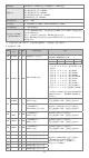
5. CR#30 is the error code register.
Note: Each error code will have a corresponding bit and should be converted to 16-bit binary numbers
(Bit0~15). Two or more errors may happen at the same time. Refer to the chart below:
Bit number 0 1 2 3
Description
Power source
abnormal
The contact is
not connected to
anything.
Reserved Reserved
Bit number 4 5 6 7
Description Reserved Reserved
average number
error
Instruction error
Bit number 8 9 10 11
Description
CH1 Abnormal
conversion
CH2 Abnormal
conversion
CH3 Abnormal
conversion
CH4 Abnormal
conversion
Bit number 12 13 14 15
Description
CH5 Abnormal
conversion
CH6 Abnormal
conversion
Reserved Reserved
6. Temperature/Digital Value Characteristic Curve
The mode of measuring Celsius (Fahrenheit) temperature:
Max.
Min.
Digital output
Temperature input
Min.
Max.
Sensor
Temperature range Digital value conversion range
°C (Min./Max.) °F (Min./Max.) °C (Min./Max.) °F (Min./Max.)
Pt100 -180 ~ 800°C -292 ~ 1,472°F K-1,800 ~ K8,000 K-2,920 ~ K14,720
Ni100 -80 ~ 170°C -112 ~ 338°F K-800 ~ K1,700 K-1,120 ~ K3,380
Pt1000 -180 ~ 800°C -292 ~ 1,472°F K-1,800 ~ K8,000 K-2,920 ~ K14,720
Ni1000 -80 ~ 170°C -112 ~ 338°F K-800 ~ K1,700 K-1,120 ~ K3,380
LG-Ni1000 -60 ~ 200°C -76 ~ 392°F K-600 ~ K2,000 K-760 ~ K3,920
Cu100 -50 ~ 150°C -58 ~ 302°F K-500 ~ K1,500 K-580 ~ K3,020
Cu50 -50 ~ 150°C -58 ~ 302°F K-500 ~ K1,500 K-580 ~ K3,020
Sensor Input resistor range Digital value conversion range
0~300Ω 0Ω ~ 320Ω K0 ~ 32000 0~300Ω 0Ω ~ 320Ω
0~3000Ω 0Ω ~ 3200Ω K0 ~ 32000 0~3000Ω 0Ω ~ 3200Ω
7. When CR#29 is set to H’5678, CR#0 ~ CR#34 can be used for PID settings with DVP04PT-S version
V3.08 and above.
PID Mode description
CR# Keep R/W
CR# Keep R/W