H.264 Standalone DVR _V2.1 USER MANUAL MANUAL_V2.
INDEX . …………………………………………… 2 Chapter one Products Introduce Introduce…………………………………………… ……………………………………………..……… ………2 1.1 Technical Parameter…………………………………………………………………………….....2 1.2 Performance……………………………………………...……………………………………..…3 ……………………………………………………………… .. 4 Chapter Two Hardware Hardware……………………………………………………………… ……………………………………………………………….. ..4 2.1 H.264 standalone 4CH/8CH/16CH DVR…………………………………………………………4 …………………………………………………………… Chapter Three Operation Operation…………………………………………………………… ……………………………………………………………..
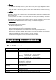
�... Power This DVR select the adaptor is DC12V; please make sure the power supply voltage before use the machine. If long time do not use the machine, please turn off the power of DVR machine, and let the electric plug away from power socket; �... safety This DVR only for indoor use, as for prevent short circuit or electric danger, please do not let the DVR in the raining or humid area.
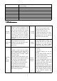
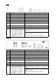
Recording mode Manual recording, timing recording , motion detection recording and external Simplex/duplex/ triplex triplex(recording, playback , LAN transmission) LAN RJ45(10M/100M self-adapting) PTZ control Yes Communication RS485×1,USB2.0×2 USB USB mouse control Hard disk drive 1or2x SATA(2TB or above) Remote control unit Yes Dimension Main board size : 220mm x 112mm Power supply AC110-230V alarm recording 1.
8ch alarm input ( alarm event mode can be set normal open or normal close selection), and turn-by-turn video loss alarm, dynamic detection alarm, the alarm device may be Alarm linkage function * Possess specific interface, achieve smoke detection censer, temperature detector, IR detector. Com-munication Possess 4ch relay switch alarm output, port flexible convenient and fast to achieve alarm input and PTZ control; * possess a standard Ethernet interface, achieve the network remote monitoring.
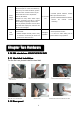
4CH Item Interface 1 VIDEO IN 4ch video input Description 2 AUDIO IN 4ch audio input 3 V-OUT 1ch video output 4 A-OUT 1ch audio output 5 VGA VGA monitor 6 NET RJ45 for internet 7 USB/ MOUSE 8 ON/OFF Power supply switcher 9 DC-12V Power adaptor port First USB for backup or upgrade system of DVR; Second USB for mouse ALARM IN:1 2 3 4 alarm input port 10 RS-485:A, B ALARM OUT: N1 alarm output port, every channel connect GND、OUT、COM; every two channel OUT, COM port is for GND;
4CH_S Item Interface 1 VIDEO IN 4ch video input Description 2 AUDIO IN 1ch audio input 3 V-OUT 1ch video output 4 A-OUT 1ch audio output 5 VGA VGA monitor 6 NET RJ45 for internet 7 USB/ MOUSE First USB for backup or upgrade system of DVR; Second USB for mouse 8 ON/OFF Power supply switcher 9 DC-12V Power adaptor port 10 No Alarm RS-485:A, B 8CH I t e m Interface Description 1 VIDEO IN 8ch video input 2 AUDIO IN 4ch audio input 3 V-OUT 1ch video output 4 A-OUT
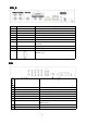
ALARM IN:IN1-IN8 alarm input port 1 RS-485:A , B 0 ALARM OUT: N1 N2 alarm output port, every channel connect GND、OUT、COM; every two channel OUT, COM port is for GND; 8CH_H Ite m Interface Description 1 VIDEO IN 8ch video input 2 AUDIO IN 8ch audio input 3 V-OUT 1ch video output 4 A-OUT 1ch audio output 5 VGA VGA monitor 6 NET RJ45 7 USB/ MOUSE 8 ON/OFF Power supply switcher 9 DC-12V Power adaptor port First USB for backup or upgrade system of DVR; Second USB for mouse AL
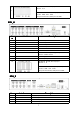
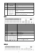
5 VGA VGA monitor 6 NET RJ45 7 USB/ MOUSE 8 ON/OFF Power supply switcher 9 DC-12V Power adaptor port First USB for backup or upgrade system of DVR;Second USB for mouse ALARM IN:A alarm input port RS-485:+, - 10 ALARM OUT: C O alarm output port, every channel connect GND、OUT、COM;, COM port is for GND; 16CH Item Interface 1 VIDEO IN 16ch video input Description 2 AUDIO IN 4ch audio input 3 V-OUT 1ch video output 4 A-OUT 1ch audio output 5 VGA VGA monitor 6 NET RJ45 for
Item Interface Description 1 VIDEO IN 16ch video input 2 AUDIO IN 4ch audio input 3 V-OUT 1ch video output 4 A-OUT 1ch audio output 5 VGA VGA monitor 6 NET RJ45 for internet 7 USB/ MOUSE 8 ON/OFF Power supply switcher 9 DC-12V Power adaptor port First USB for backup or upgrade system of DVR ; Second USB for mouse ALARM IN:8CH 10 alarm input port RS-485:A, B ALARM OUT: N1 N2 for alarm output port, every channel connect C and O;COM port is for GND; 2.1.
4 way switching value alarm output, selectable in normally open contact, also selectable in normally closed contact, the external alarm device should be need Vcc; Chapter Three Operation 3.1Operation instruction 3.1.
1 【POWER】 2 【DEV】 Select DVR1,2,3,… 3 【MENU】 Access main menu This button is used as“enter”and“ok” key in most circumstances Switch capital letter/small letter/symbol input on soft keyboard 11 【 ENTER 】 【OK】 12 【SWITCH】 13 【MODE】 Switching of Lens IRIS/FOCUS/ZOOM modes 14 【PTZ】 15 【+/-】 Access/exit from PTZ control under preview state Volume or number increase/reduction Select item of the list 16 【 ZOOM IN/OUT】 Lens control 17 【MUTE】 Mute enable/disable 18 【0~9 10+】 Digital inpu
Right click mouse, popping the shortcut menu, as follows; 2 Right click mouse 。 Through the menu can be switching preview screen window mode, start replays, PTZ control. Four pictures playback mode, the point of the right mouse button, Can in a single picture, four pictures, eight pictures (8 road playback), 16 screen (16 road playback), broadcast control switch view show or hide broadcast control bar.
Button Description Button Main Menu Description PTZ control Wizard language Alarm control Multi channel Display setup Recording Control Exit Playbake Bake up If before starting, the system not to install hard disk, into the system, will tip: system didn't detect any hard disk connection! 3. 3 Shutdown 3.3 � There are two safety mode for Shutdown Enter【Exit】,select【Power Down】.
While the DVR-4108 running, directly to pull up the power cable of DVR-4108, please avoid as much as possible to do it. (specially while the DVR recording). Caution: In some area, the power supply is irregularity, it will cause the DVR-4108 working not normal-operation, the DVR-4108 will be damaged in serious. In this surroundings, suggest select the stabilized voltage supply. 3.4 Multi Channel 1/4/8/9/16 preview screen mode switch 3.
channel. Manual recording ” permission. Note: Manual recording operational requirement the user should have “recording recording” Please make sure the hard disk drive has been installed and it has been formatted. Input manual recording operation menu 1)Input Single click right key of mouse or In main menu=> recording control can into manual recording operation menu.
Synchronous/asynchronous play Voice adjustment frame by frame 1/4/8/9/16 screen(switch image) Speed slow Hide / display list Speed normal recording date Speed fast Play/pause/stop Sound off/on rewind Note: 1) During playback the Playback Tool will show the file playback speed, channel, timing, playback speed etc.
【Set】Click 【Start Tour】the trajectory of said no corresponding, click the 【add Preset 】 and 【delete Preset point 】, 【Clear Tour】 the cruise lines. 【Start Tour】begin to track record, was registered date 【 end Tour】,thus set up from the corresponding track circuit. 【Left Limit】Began to limit scanning Settings, was registered date 【right Limit 】, thus set up corresponding limit scanning. 【Add Preset】Add presets point to the cruise lines. 【Delete Preset】Cruise lines from deleting preset points.
3.9 Alarm control 【Set Alarm】Selection need protection channel, click confirm corresponding channel after in protection status 【Clear Alarm】Remove protection condition, not alarm input to react 【Alarm Output】Open the corresponding alarm output 【All】Can choose all the channels 3.10 Display Adjust (1)Video 【Video Effect】Optional: standard, downy, sharp, custom. 【Default】Restoring default effect, for custom video effects, copy standard effect parameters.
【Device】Optional: VGA output, TV output etc display output device. 【Default】Restoring default display parameters. Through the slider fluctuation sliding, respectively adjustable brightness, contrast and saturation, tonal, etc. (3)Setup 【 Device 】 Optional: VGA output, TV output etc display output devices, the system may support multiple equipment and output. 【Resolution】Setting the resolution of the display device. Chapter Four Menu Operation Guide 4.
【Channel】Choose the need to install passage "whole" says setting all channels. 【Image Size】CIF/HALF D1/D1 (only in whole function model) 【Encoding Mode】Including fixed bitrate, dynamic bitrate. 【Image Quality】Client-side image quality, the higher the quality the clearer. Choice scope: minimum, low, general, high, highest 【Frame Rate】 Can click on the button manually input, 1 ~ 25 frames per second (PAL) or 1 ~ 30 frames per second (NTSC) continuous adjustable.
【Channel】Choose the need to install passage "whole" says setting all channels. 【Channel Name】Can manual corresponding input channel's name 【Channel Display】Can choose according to the requirements of users don't use, the top-left corner, left, lower, middle and downward, upper, right, and lower. 【 Time Display 】 Can choose according to the requirements of users don't use, the top-left corner, left, lower, middle and downward, upper, right, and lower.
【Channel】Choose regional channels, yuntai Settings "whole" says setting all channels 【PTZ Protocol】Yuntai equipment communication protocol ★Note: yuntai parameter Settings every channel need after completion in Settings of gc1318 alone. 【PTZ Address】Yuntai equipment address, digital range 0 to 255. ★Note: here with the address must be consistent ball machine address, we can't control the ball machine. 【Bit-rate】Yuntai equipment baud rate.
【Channel】Choose need to set up mobile testing area passage "whole" says setting all channels 【Sensitivity Setting】Can be set to give: minimum, low, general, high, highest 【Detection Area】Click Settings enter. Green area for dynamic test, grey areas design.ferroconcrete-brick undefended area for. Press the mouse left key to drag on the lower detection area to the right, press the mouse button clearance.
【DHCP】After checked automatic assignment device will get IP address, subnet mask, the default gateway, the DNS server, etc 【UPnP】Can choose according to the requirement 【IP Address】Network logic address can according to the requirements set 【Subnet Mask】Server subnet mask 【Default Gateway】Server gateway 【DNS Server】DNS server addresses 【Server Port】Data port, initial socket for 7777 【HTTP Port】the default port for 80. If change, when using IE browser, need to monitor the IP address, adding new socket.
【DDNS Service】Dynamic DNS provider website 【DDNS Domain】Dynamic domain name, soft keyboard and hard keyboard can be input. 【DDNS Account】Login domain name service provider website user name 【DDNS Password】Login domain name service provider website password Tip: through the dynamic DNS server. Support dynamic DNS. (4)Email 【SSL Protocol】Sending E-mail in use safety network connection 【Test Email】Send an email to the recipient mailbox test 【Email Address】The recipient's email address.
【List Rule】According to the requirement to choose: don't use, allow access, refused to visit. 【Starting IP】Display IP address started section 【Ending IP】Display IP address end segments 【Add】On the basis of the need for added 【Delete】According to the need to delete 4.4 System Setup (1)Time 【System Language】Used in a remote remote device control more hard disk video recorder occasions, only in remote controls address and hard disk video recorder Numbers identical to remote operation.
【Set Time】Confirm modification system of time (2)HDD Management 【Disk Full】When video disk full system how to deal with, "said system will be automatic coverage the earliest video files continue covering video," stop video "says system to stop the current video. 【File Time】Says automatic generation video files interval, the set range 5-120 minutes.
According to the save button modified users. 【Edit Password】Select the account, input to modify current user password, and enter the account password and confirmation password new. According to the save button for password changing. The password can be set to 0 ~ 8 bits (4)Alarm Setup 【Alarm Input】Choose corresponding alarm channel, "all" setup all channel said.
4.5 System Management (1)System Upgrade Show the system hardware versions, software version, release dates. Click [software upgrade 】, the system began to automatically detect and upgrade file. Note: equipment currently support upgrades: local USB mode, IE mode, the client software. USB mode: former ensure USB device to connect upgrade normal, as upgrade program has copy USB devices in the root directory. According to the interface can upgrade operation hints.
(3)Default Restoring default can restore selected according to need. The system restore to the default configuration state out, can according to the menu options choose to restore the corresponding Settings. Tip: menu color, language, time date format, video format, IP address, the user account, etc will not be restored. (4)Exception Handling 【Exception Type】Choose abnormalities: hard disk full, hard disk errors, network connection. 【Buzzer】When abnormality, choose whether to allow the buzzer hints.
Chapter Five IE Preview 5.
Pretermission IP address is 192.168.1.110 5.2 System Settings Point , As the picture ,You can set up language directory,After all to save you set.
33
34
5.
36
37
38
Chapter Six FAQ (Frequently Asked Questions) 01:Why the DVR did not run after connect the power supply? ①Please check the power switch turn on or off at the rear panel of DVR. ②Please check if the turn on DVR operation correct or not? ③If you select the adaptor +12V, 5A or above? (8ch 5A, 16ch 220V 200W) 02:Still stop over on the boot-strap frame? Physical damaged in hard disk drive Boot manager abnormal.
②if the video connected with TV or VGA monitor properly? Check if there is any video signal input? And make sure the line faulty or not? 09:Why does the video like water wave, to appear obstruction distortion? ①if there is short circuit, open circuit or insufficient solder and connection failure of video cable? ②If the video cable obstruction by high voltage interference, please separate the video and high voltage in linkup cabling, at the meantime, please select the better quality, shield video cable for t
Postscript Product parameter Table 4CH Compress 16CH H.264 baseline profile@L3.1 standard Video in 8CH BNC(1.0Vp-p/75Ω) BNC(1.0Vp-p/75Ω) BNC(1.0Vp-p/75Ω) Video out 1TV BNC(1.0Vp-p/75Ω)/ 1VGA 1TV BNC(1.0Vp-p/75Ω)/ 1VGA 1TV BNC(1.
Mobil platform RS485 Communication port Hard Disc USB interface Remote control Power adapter Working temperature Working humidity Naway.CAB;symbian v3;symbian v5;Naway-Android;iphone,Blackberry PTZ control PTZ control PTZ control RS485×1,USB2.0×2 RS485×1,USB2.0×2 RS485×1/2,USB2.