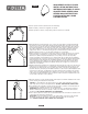
50560 SERIES–SUPPLY ELBOW INSTALLATION INSTRUCTIONS 43934 INSTRUCCIONES PARA EL CODO ABASTECEDOR–SERIES 50560 SÉRIES 50560–INSTRUCTIONS D’INSTALLATION DU COUDE D’ALIMENTATION 1. Remove present shower head and shower arm with flange. 1. Quite la cabeza y el brazo de la regadera con la brida. 1. Retirez la pomme de douche, le tuyau de la pomme de douche et la collerette. 2.
LIFETIME FAUCET AND FINISH LIMITED WARRANTY OF LOSS OR DAMAGES ARE EXCLUDED. Proof of purchase (original sales receipt) from the original consumer purchaser must be made available to Delta for all warranty claims. THIS IS THE EXCLUSIVE WARRANTY BY DELTA FAUCET COMPANY, WHICH DOES NOT MAKE ANY OTHER WARRANTY OF ANY KIND, INCLUDING THE IMPLIED WARRANTY OF MERCHANTABILITY.
51105, 51205, 51308 & 51405 SERIES WALL BAR HAND SHOWER UNIT INSTALLATION INSTRUCTIONS 86682 SERIES 51105, 51205, 51308 Y 51405 INSTRUCCIONES PARA LA INSTALACIÓN DE LA BARRA EN LA PARED PARA SOSTENER LA REGADERA MANUAL SERIA 51105, 51205, 51308 ET 51405 INSTRUCTIONS D’INSTALLATION DE LA COULISSE DE DOUCHE À MAIN Write purchased model number here. Escriba aquí el número del modelo comprado. Inscrivez le numéro de modèle ici.
1 Slide Bar Barra deslizable Coulisse Select wall position for wall bar or wall mount bracket based on family’s needs. NOTE: Locate so there will be slack in the hose when hand shower is in extreme up or down position. Follow the mounting instructions for your specific model. Elija la posición en la pared para la barra de pared basada en las necesidades de su familia.
Slide Bar Barra deslizable Coulisse 51308 Series/Series/Seria 3 4 1 2 5 23 3/4" (603 mm) 4 3 1 5 2 SLIDE BAR INSTALLATION Locate stud for secure mounting. The sheaths (1) are adjustable, loosen sheath set screws (2) to adjust mount location. Tighten sheath set screws once mount location is selected. Mark mounting locations, suggest 23 3/4” (603mm) on center. Loosen the escutcheon set screws (5). Remove the escutcheons from the wall bar assembly.
Wall Mount Montaje en la pared Supports Muraux Shower Mount Regadera en la pared Porte-douche 55411, 55421, 55433 & 55445 Series / série A. B. 3 5 2 4 3 2 6 8 1 7 1 1 54411, 54421, 54433 & 54445 Series / série WALL MOUNT BRACKET INSTALLATION Models 55411, 55421, 55433 & 55445 - Select wall position for hand shower wall mount based on family’s needs. Remove the locknut (1) from the bracket (2). Using the bracket (2), mark the 2 holes in the desired location.
2 A. A. Ensure gasket (1) is inserted into the hose (2). Connect the hose to your designated water supply. B. Connect tapered end of hose to hand shower. Connect tapered end of hose to hand shower: Seat the gasket (1) firmly into the hose nut (2). Carefully align the thread of the tapered end of the hose (2) directly to the hand shower. Hand Tighten – do not use a wrench or pliers. Then place the hand shower into the wall mount holder or shower mount holder. A.
CLEANING AND CARE Care should be given to the cleaning of this product. Although its finish is extremely durable, it can be damaged by harsh abrasives or polish. To clean, simply wipe gently with a damp cloth and blot dry with a soft towel.
BODY SPRAY ROCIADOR PARA EL CUERPO BUSE DE PULVÉRISATION 78285 Models/Modelos/Modèles SH84100s, SH84101s, SH84102s, SH84103s, SH5000s, SH5002s, SH5003s, SH5005s, Series/Series/Seria SH84100s SH84101s SH84102s SH84103s SH5003s SH5005s SH5002s SH5000s ▲ Specify Finish / Especifíque el Acabado / Précisez le fini Limited Warranty on Delta® Faucets Parts and Finish All parts (other than electronic parts and batteries) and finishes of this faucet are warranted to the original consumer purchaser to be
A. B. 2 1 1 3 4 Installing the Spray Head B. Apply wrench (3) to flats on pop-out mechanism (1), as shown, to stop rotation during spray head installation. Note: The wrench will only properly fit the flats in one direction. Insert and thread spray head (4) into pop-out mechanism (1) until threading stops. Note: Take care not to over tighten the spray head. Store wrench (3) for future use. A.
78403 HYDRACHOICE™ BODY SPRAY TRIM ACCESORIO DEL ROCIADOR PARA EL CUERPO HYDRACHOICE™ FINITION DU JET CORPOREL HYDRACHOICEMC T50010s Models/Modelos/Modèles T50010s & T50210s Series/Series/Seria T50210s ▲ Specify Finish / Especifíque el Acabado / Précisez le fini Limited Warranty on Delta® Faucets Parts and Finish All parts (other than electronic parts and batteries) and finishes of this Delta® faucet are warranted to the original consumer purchaser to be free from defects in material and workmanship
Installing the Trim Module / Instalación del módulo del accesorio / Installation du module de finition A. C. T50010▲ T50210▲ 5 1/4" 1/4" 1 1/4" 1/4" 4 4 6 B. 6 D. 4 2 5 2 3 Bottom View Debajo / Au-dessous 6 A. Remove the test cap/plaster guard (1) from the previously installed rough body and store for future use. B. Apply the provided 100% plumbing silicone / adhesive (4) to back outer edge of trim module (2). Insert trim module (2) and tighten using tool (3).
Cleaning the Trim Module Filter / Limpieza del filtro del módulo / Nettoyage du filtre du module C. A. E. 7 7 2 5 3 B. F. D. 2 7 2 3 5 A. Gently pry off the escutcheon starting at the weep hole located on the bottom of escutcheon (5). Note: Take care not to damage the escutcheon finish. B. Remove the trim module using tool (3). C. Carefully remove filter screen (7) and flush with water until clear of debris. D. Place the cleaned filter screen (7) back into the trim module (2). E.
T50010▲ RP82501 Trim Module 1.0 GPM flow rate Módulo del Accesorio Caudal de 1,0 GPM Module de finition Débit de 1,0 gpm T50210▲ RP78987 Silicone Silicona Siliconé RP82501 Trim Module 1.
MultiChoice® Valve Trim with Diverter Installation Instructions Owners Manual Write purchased model number here. 3/32" 92345 T27859, T27867, T27897, T27899, T27959, T27967, T27997 & T27999 Series You May Need Table of Contents: Warranties ............................................................................... Page 2 Installation Instructions ........................................................... Pages 3 - 7 Clean and care.....................................................................
Lifetime Faucet and Finish Limited Warranty Parts and Finish All parts (other than electronic parts and batteries) and finishes of this Delta® faucet are warranted to the original consumer purchaser to be free from defects in material and workmanship for as long as the original consumer purchaser owns the home in which the faucet was first installed or, for commercial users, for 5 years from the date of purchase.
Installation 1 Cartridge Installation A. B. 4 3 2 2 1 1 3 2 Turn off water supplies. Remove cover (1), bonnet nuts (2) and test caps (3) from the rough-in body (4). Place a bucket or small container over the front of the valve body and slowly open the water supplies to flush any debris from the supply lines before installing the cartridge. Turn the water supplies back off. Insert adapter assembly (1) into rough-in body (2).
Installation 2 Diverter Cartridge Installation A. B. 5 2 2 3 4 1 1 5 For Bonnet Installation Slide bonnet nut (1) over diverter sleeve (2) and thread into rough-in body. Hand tighten securely. FOR DIVERTER CARTRIDGE INSTALLATION: Apply silicone lube to the o-ring (2) to make the diverter sleeve (3) easier to install diverter cartridge. A light coating of plumbers grease applied to o-rings (4) may aid in assembly.
Installation 3 Trim Installation A. B. 1 3 2 6 4 5 1 3 2 Drip notch Trim Sleeve Installation Slide trim sleeve (1) over the bonnet (2), cartridge and rough-in body. Ensure sleeve is properly positioned over the front of cartridge. Escutcheon Installation For finished wall thickness up to 1 1/8". Secure the backplate (1) to the rough-in body (2) using 4 screws (3) provided. Note: Be sure backplate is oriented front side forward and markings are visible.
Installation 4 Installation and Adjustment of the Rotational Limit Stop A. B. 2 1 Place the rotational limit stop (1) in volume handle (2) and rotate to the mixed position (if required). DO NOT SECURE WITH SCREW. Turn on water supplies; let the water run until both hot and cold water is as hot/cold as possible. Place thermometer in a plastic tumbler, and hold the tumbler in the water stream. Record the temperature reading. Hotter 1 C.
Installation 5 Potential scald or thermal shock injury could result due to cross flow if outlet at the shower is blocked or restricted (e.g., pause control on showerhead). Be sure to point showerhead away from you when re-starting flow or install inlet check valves on both supply lines to prevent possible injury. 6 Diverter handle Installation B. 2 1 3 4 Diverter Handle Installation Slide diverter handle (1) onto trim sleeve (2). Using a allen wrench, insert set screw (3) into handle (1).
Diverter Handle Reference Sheet Water Flow For 3 Function Diverter / Flujo de agua para Desviadores de 3 posiciones / Écoulement de l’eau pour les inverseurs à 3 positions 1st Position 1 ª posición 1ère position Outlet 3 Outlet 2 Salida 3 Salida 2 Sortie 3 Sortie 2 Outlet 2 Salida 2 Sortie 2 3rd Position 3 ª posición 3e position 2nd Position 2 ª Posición Outlet 1 Salida 1 2e position Sortie 1 Outlet 1 Salida 1 Sortie 1 Outlet 3 Salida 3 Sortie 3 Outlet 3 Salida 3 Sortie 3 Outlet 2 Salida 2 Sor
Clean and Care Care should be given to the cleaning of this product. Although its finish is extremely durable, it can be damaged by harsh abrasives or polish. To clean, simply wipe gently with a damp cloth and blot dry with a soft towel. Maintenance Faucet leaks from showerhead: SHUT OFF WATER SUPPLIES. Replace valve cartridge RP46463 or RP32104 See Helpful Hints 1, 2, 3 & 4. Helpful Hints: 1.
92345 Rev.
Manual para propietarios T27859, T27867, T27897, T27959, T27967 & T27997 Serie Escriba el número del modelo aquí. Puede necesitar Tabla de contenido: Garantía ............................................................................... Página 2 Instrucciones de instalación ................................................ Páginas 3 - 7 Limpieza y cuidado .............................................................. Página 9 Mantenimiento ................................................................
Garantía limitada de por vida de la llave de agua y acabado Piezas y Acabado Todas las piezas (menos las piezas electrónicas y las pilas) y acabados de esta llave de agua - grifo Delta® están garantizados al consumidor comprador original, de estar libres de defectos en materiales y mano de obra durante el tiempo que el comprador original sea dueño de la casa en la cual la llave de agua fue instalada por primera vez o, para los usuarios comerciales, por cinco (5) años desde la fecha de compra.
Instalación 1 Instalación del cartucho A. B. 4 3 2 2 1 1 3 2 Cierre los suministros de agua. Quite la tapa (1), tuercas tapas (2) y las tapas de prueba (3) del cuerpo de la tubería preliminar detrás de la pared (4). Coloque una cubeta o recipiente pequeño sobre el frente del cuerpo de la válvula y abra lentamente los suministros de agua para eliminar cualquier residuo de las líneas de suministro antes de instalar el cartucho. Cierre otra vez el agua de suministro.
Instalación 2 Instalación del cartucho de desvío A. B. 5 2 2 3 4 1 1 5 PARA LA INSTALACIÓN DEL CARTUCHO DE DESVÍO: Aplique lubricante de silicona a la junta tórica (2) para facilitar la instalación del cartucho desviador con el casquillo desviador (3). La aplicación de una ligera capa de grasa de plomeros a las juntas tóricas (4) puede facilitar el montaje.
Instalación 3 Instalación del accesorio A. B. 1 2 3 4 5 1 3 2 Instalación del casquillo del accesorio Deslice el casquillo del accesorio (1) sobre el casquete (2), el cartucho y el cuerpo de la tubería preliminar. Asegúrese que el casquillo está correctamente colocado sobre el frente del cartucho. Instalación del chapetón Para paredes acabadas de un grosor hasta 1 1/8". Fije la placa posterior (1) al cuerpo de la unidad de las tuberías preliminares (2) usando los 4 tornillos (3) proporcionados.
Instalación 4 Instalación y ajuste del tope del límite rotacional A. B. 1 Coloque la perilla para el control de temperatura (1) en la palanca de volumen y gire a la posición mixta (si es necesario). NO FIJE CON EL TORNILLO. Abra los suministros de agua; deje que el agua fluya hasta que esté lo más caliente/fría posible. Coloque un termómetro en un vaso plástico, y sostenga el vaso bajo el chorro de agua. Registre la lectura de la temperatura. Hotter 1 C.
Installation 5 Existe la posibilidad de lesión por escaldadura o de choque térmico resultante de un flujo cruzado en el caso que la salida de la regadera/ducha está bloqueada o restringida (por ejemplo, pause el control de la cabeza de la regadera/ducha). Asegúrese de apuntar la regadera/ducha alejado de usted cuando vuelva a iniciar el flujo o instale las válvulas de retención de la entrada en ambas líneas de suministro para evitar posibles lesiones. 6 Instalación del desviador de la manija B.
Hoja de referencia para la manija desviadora Water Flow For 3 Function Diverter / Flujo de agua para Desviadores de 3 posiciones / Écoulement de l’eau pour les inverseurs à 3 positions 1st Position 1 ª posición 1ère position Outlet 3 Outlet 2 Salida 3 Salida 2 Sortie 3 Sortie 2 Outlet 2 Salida 2 Sortie 2 3rd Position 3 ª posición 3e position 2nd Position 2 ª Posición Outlet 1 Salida 1 2e position Sortie 1 Outlet 1 Salida 1 Sortie 1 Outlet 3 Salida 3 Sortie 3 Outlet 3 Salida 3 Sortie 3 Outlet 2
Limpieza y Cuidado Se debe tener cuidado con la limpieza de este producto. Aunque su acabado es extremadamente resistente, puede ser dañado por abrasivos o pulimentos ásperos. Para limpiar, simplemente frote con un paño húmedo y seque con una toalla suave. Mantenimiento Si hay filtración de agua desde la llave de agua/grifo de la regadera: CIERRE LOS SUMINISTROS DE AGUA. Reemplace la válvula de cartucho o RP46463 RP32104 Vea Consejos útiles 1, 2, 3 y 4 Sugerencias útiles: 1.
92345 Rev.
Manuel d'utilisation T27859, T27867, T27897, T27959, T27967 & T27997 Series Inscrivez le numéro du modèle acheté ici. Ce dont vous pouvez avoir besoin Table des matières: Garanties ................................................................................... Page 2 Instructions d'installation ........................................................... Pages 3 - 7 Nettoyage et entretien ............................................................... Page 9 Maintenance ...............................
Garantie à vie sur le robinet et garantie limitée sur le fini Pièces et finis Toutes les pièces et tous les finis de ce robinet Delta® sont protégés contre les défectuosités du matériau et les vices de fabrication par une garantie qui est consentie au premier acheteur et qui demeure valide tant que celui-ci demeure propriétaire de la maison dans laquelle l’accessoire a été installé. Dans le cas d’une utilisation commerciale, la garantie est de 5 ans à compter de la date d’achat.
Installation 1 Installation de la cartouche A. B. 4 3 2 2 1 1 3 2 Fermez les robinets d’alimentation. Retirez le capuchon (1), les écrous-chapeaux (2) et les capuchons d'essai (3) du corps de robinetterie brute (4). Placez un seau ou un petit contenant sur l’avant du corps de soupape et ouvrez lentement les robinets d’arrêt pour évacuer les corps étrangers de la tuyauterie avant d’installer la cartouche. Fermez de nouveau les robinets d’arrêt.
Installation 2 Installation de la cartouche de l’inverseur A. B. 5 2 2 3 4 1 1 5 INSTALLATION DE LA CARTOUCHE DE L'INVERSEUR Ajoutez du lubrifiant à base de silicone au joint torique (2) pour faciliter la pose du manchon de l'inverseur (3) et la cartouche de l’inverseur. Vous pouvez enduire les joints toriques (4) d’un peu de graisse de plomberie pour faciliter l’assemblage.
Installation 3 Installation de la pièce de finition A. B. 1 2 3 4 5 1 3 2 Installation du manchon de finition Glissez le manchon de finition (1) sur le chapeau (2), la cartouche et le corps de robinetterie brute. Assurez-vous que le manchon est bien positionné sur l'avant de la cartouche. C. Installation de la plaque de finition Installation dans un mur fini d’une épaisseur maximale de 1 1/8 po. Fixez la plaque arrière (1) au corps de robinetterie brute (2) au moyen des quatre vis (3) fournies.
Installation 4 Installation et réglage de la butée de température maximale A. B. 1 Placez le bouton de réglage de température (1) sur la manette de réglage de débit et tournez-le jusqu’à la position de mélange (au besoin). NE LE FIXEZ PAS AVEC LA VIS. Rétablissez l’alimentation en eau. Laissez couler l’eau jusqu’à ce que l’eau froide soit aussi froide que possible et que l’eau chaude soit aussi chaude que possible.
Installation 5 Possibilité d’ébouillantage ou de choc thermique pouvant causer des lésions en raison d’une inversion de la circulation de l’eau si la sortie de la douche est bloquée ou limitée (p. ex. : circulation bloquée par la commande d’arrêt sur la pomme de douche). Avant d’ouvrir le robinet, déplacez la pomme de douche pour ne pas vous faire arroser. Vous pouvez également installer des clapets de non-retour sur les deux tuyaux d'alimentation en eau pour éliminer les risques de blessures.
Fiche de référence de la manette de l'inverseur Water Flow For 3 Function Diverter / Flujo de agua para Desviadores de 3 posiciones / Écoulement de l’eau pour les inverseurs à 3 positions 1st Position 1 ª posición 1ère position Outlet 3 Outlet 2 Salida 3 Salida 2 Sortie 3 Sortie 2 Outlet 2 Salida 2 Sortie 2 3rd Position 3 ª posición 3e position 2nd Position 2 ª Posición Outlet 1 Salida 1 2e position Sortie 1 Outlet 1 Salida 1 Sortie 1 Outlet 3 Salida 3 Sortie 3 Outlet 3 Salida 3 Sortie 3 Outle
Nettoyage et entretien Ce produit doit être nettoyé avec soin. Bien que le fini soit extrêmement durable, il peut être abîmé par des agents de polissage puissants ou des nettoyants fortement abrasifs. Pour le nettoyer, il suffit de le frotter doucement avec un chiffon humide, puis de l’éponger avec une serviette douce. Maintenance Fuite du robinet par la pomme de douche: FERMEZ LES ROBINETS D'ALIMENTATION. Remplacez la cartouche de soupape RP46463 ou RP32104 Reportez-vous aux conseils utiles 1, 2, 3 et 4.
For illustrative purposes, the replacement parts for the T27 Series Classic Collection are shown on the following page. For replacement parts on all other collections, please refer to the parts diagrams available on www.deltafaucet.com. Para los fines ilustrativos, las piezas de repuesto para la Colección Clásica de la Serie T27 se muestran en la siguiente página. Para las piezas de repuesto sobre todas las demás colecciones, por favor refiérase a los diagramas de piezas disponibles en www.deltafaucet.com.
RP90543 Thick Wall Installation Kit Juego de piezas para la instalación en paredes gruesas Trousse d’installation pour mur épais For finished wall thickness over 1 1/8” up to 2 1/8” (Order Separately) Para paredes acabadas de un grosor mayor de 1 1/8” hasta 2 1/8” (ordene por separado) Installation dans un mur fini d’une épaisseur de 1 1/8 po à 2 1/8 po (commandez séparément) 11 92345 Rev.
T27859, T27959 Models / Modelos / Modèles RP84928 Escutcheon Assembly & Screws Ensamble de la chapa y tornillos Plaque de finition et vis RP84932p Trim Nut Tuerca del accesorio Écrou de finition RP84973p Diverter Handle, Set Screw & Button Manija desviadora, tornillo de fijación y botón Manette de l’inverseur, vis de calage et bouton RP84925 Valve Seal Sello de la válvula Garniture d’étanchéité RP84972p Set Screw & Button Tornillo de fijación y botón Vis de calage et bouton RP84970p (T27859) RP84971p (T2
T27867, T27967 Models / Modelos / Modèles RP84932p Trim Nut Tuerca del accesorio Écrou de finition RP84985p Diverter Handle, Set Screw & Button Manija desviadora, tornillo de fijación y botón Manette de l’inverseur, vis de calage et bouton RP84928 Escutcheon Assembly & Screws Ensamble de la chapa y tornillos Plaque de finition et vis RP84925 Valve Seal Sello de la válvula Garniture d’étanchéité RP84984 Set Screw & Button Tornillo de fijación y botón Vis de calage et bouton RP84936p Trim Sleeve Casquill
T27897, T27997 Models / Modelos / Modèles RP84928 Escutcheon Assembly & Screws Ensamble de la chapa y tornillos Plaque de finition et vis RP84932p Trim Nut Tuerca del accesorio Écrou de finition RP100179p (T27997 only) Diverter Handle, Set Screw & Button Manija desviadora, tornillo de fijación y botón Manette de l’inverseur, vis de calage et bouton RP84925 Valve Seal Sello de la válvula Garniture d’étanchéité RP84931p (T27897 only) Diverter Handle, Set Screw & Button Manija desviadora, tornillo de fijac
T27899, T27999 Models / Modelos / Modèles RP91915p Diverter Handle, Set Screw & Button Manija desviadora, tornillo de fijación y botón Manette de l’inverseur, vis de calage et bouton RP84928 Escutcheon Assembly & Screws Ensamble de la chapa y tornillos Plaque de finition et vis RP84932p Trim Nut Tuerca del accesorio Écrou de finition RP84925 Valve Seal Sello de la válvula Garniture d’étanchéité RP84972p Set Screw & Button Tornillo de fijación y botón Vis de calage et bouton RP84936p Trim Sleeve Casqui
Delta Faucet Company Product Service 55 E. 111th Street Indianapolis, IN 46280 92345 Rev.
IMPORTANT DOCUMENTS ENCLOSED CAUTION: To reduce the risk of injury due to hot water burns, make sure the enclosed labels are applied where specified on the label. DOCUMENTOS IMPORTANTES INCLUIDOS AVISO: Para reducir el riesgo de lesión por quemaduras de agua caliente , asegúrese que las etiquetas incluidas se han aplicado donde se ha especificado en la etiqueta.
NOTICE TO INSTALLER: Place this label on the water heater next to the temperature adjustment knob. WARNING: These series of tub/shower valves do not adjust automatically for changes in temperature at the hot water heater or inlet.
MULTICHOICE® UNIVERSAL WITH INTERGRATED DIVERTER ROUGH 91557 Multichoice® Universal con DESVIADOR INTERGRADO INTERNO ROBINETTERIE BRUTE MULTICHOICE® UNIVERSELLE AVEC INVERSEUR INTÉGRÉ Model/Modelo/Modèle R22000 and R22000-WS Series/Series/Seria Write purchased model number here. Escriba aquí el número del modelo comprado. Inscrivez le numéro de modèle ici.
1 Standard Installation B. A. C. 3 Thick Wall Installation 3 5 1 5 4 2 3 2 2 1 1 4 A. SHUT OFF WATER SUPPLIES. Consider the type and thickness of your finished wall before placing your stringer back plate. Install the body (1) so the surface of the finished wall is flush with the front of the rough-in box (2) ± 1/4". Mount body using the two stringer mounting holes (3) on the body. Note: Remove cover (4) to access mounting holes.
2 A. B. C Copper Tubing Tubería de Cobre Cuivre 3 H 3 H C Iron Pipe Hierro Fer 2 H 1 C C PEX 2 H 4 1 A. Connect valve body to water supplies using the proper fittings for your valve body type (copper tubing, iron pipe or Pex). Note: For PEX, be sure to use the right fitting for crimping and the right tool for cold expansion. If any of the three outlet ports is to be unused, seal the port with a pipe plug. Note: On rough-in box (C) is the cold inlet port and (H) is the hot inlet port.
3 4 6 1 6 7 3 2 1 6 3 5 2 1 4 Connect top outlet port (1) to shower pipe with proper fittings. PRESSURE TESTING & FLUSHING THE INSTALLATION Conecte la salida de arriba (1) a la tubería de la regadera con los accesorios apropiados. PRUEBA DE PRESIÓN Y LIMPIEZA DE LA INSTALACIÓN À l’aide des raccords appropriés, raccordez l’orifice supérieur (1) au tuyau de la douche.
Wall Finish Template / Terminado plantilla de pared / Gabarit pour le mur fini NOTICE Failure to follow instructions for finished opening may result in product or property damage and water leak and may void the warranty. AVISO El no seguir las instrucciones para el acabado de la apertura, pudiera resultar en daños al producto o a la propiedad y la filtración de agua pudiera anular la garantía.
Water Flow For 3 Function Diverter / Flujo de agua para Desviadores de 3 posiciones / Écoulement de l’eau pour les inverseurs à 3 positions 1st Position 1 ª posición 1ère position 2nd Position* 2 ª Posición* 2e position* Outlet 1 Salida 1 Sortie 1 Outlet 3 Outlet 2 Salida 3 Salida 2 Sortie 3 Sortie 2 Outlet 2 Salida 2 Sortie 2 3rd Position 3 ª posición 3e position Outlet 1 Salida 1 Sortie 1 Outlet 3 Salida 3 Sortie 3 Outlet 3 Salida 3 Sortie 3 Outlet 2 Salida 2 Sortie 2 In / Entrada / Entrée In /
Replacement Parts Piezas de Repuesto Pièces de rechange RP84875 Rough-In Box and Screws Componente de las tuberías internas y tornillo Corps de robinetterie brute avec vis RP83940 Bonnet Bonele/Capuchon Chapeau RP46078 Test Cap Tapa de Prueba Capuchon d’essai RP20032 Plug Tapon Bouchon RP46078 Test Cap Tapa de Prueba Capuchon d’essai RP22734 Bonnet Bonele/Capuchon Chapeau RP50366 Stop Tope Butée RP46076 Cover Cubierta Couvercle RP50366 Stop Tope Butée Other useful accessories that may be purchased se
Limited Warranty on Delta® Faucets Parts and Finish All parts (other than electronic parts and batteries) and finishes of this Delta® faucet are warranted to the original consumer purchaser to be free from defects in material and workmanship for as long as the original consumer purchaser owns the home in which the faucet was first installed or, for commercial users, for 5 years from the date of purchase. In the United States and Mexico: Delta Faucet Company Product Service 55 E.
HYDRACHOICETM ROUGH-IN BODY 75391 CUERPO HYDRACHOICETM PARA LA INSTALACIÓN DENTRO DE LA PARED CORPS DE ROBINET HYDRACHOICEMC Model/Modelo/Modèle R50200 Write purchased model number here. Escriba aquí el número del modelo comprado. Inscrivez le numéro de modèle ici.
RP100576 Test Cap & O-Ring Tapa de prueba y junta tórica Bouchon d’essai et joint torique 2 75391 Rev.
1 Finished wall Pared acabada Mur fini 3 4 3/16" (106 mm) 3" ± 3/8" 3 po ± 3/8 po Stringer face Rostro autónomo Stringer figure 2 2 1 SHUT OFF WATER SUPPLIES. Consider the type and thickness of your finished wall before placing the stringer back plate. Install the valve body (1) so the surface of the finished wall is 3" ± 3/8" from the front face of the stringer (2), using the stringer mounting holes (3) on the valve body.
2 A. B. 1 1 4 Connect valve body (1) 1/2"-14 NPT inlet to water supplies using the proper fittings. WARNING: No back to back installation is allowed with this product. B. If soldering is required for any connection, remove test cap / plasterguard (4) before soldering. WARNING: avoid high temperatures. Be sure to reinstall the test cap / plasterguard (4) after soldering. A. Conecte el cuerpo de la válvula (1) entrada del 1/2" - 14 NPT a los suministros de agua usando los accesorios apropiados.
3 4 Body Spray Roughs Rociadores para el cuerpo terreno Buses de pulvérisation brouillon 1/2" (12.7 mm) Pipe 1/2" (12.7 mm) Tubo Tuyau 1/2 po (12.7mm) 4 Water supply from diverter Suministro de agua de desviador L’approvisionnement en eau de dérivation PRESSURE TESTING & FLUSHING THE INSTALLATION Prior to testing, reinstall test cap (4). Tighten securely. Check for leaks. After testing remove the test cap / plasterguard and flush system. Reinstall test cap / plasterguard (4).
Limited Warranty on Delta® Faucets Parts and Finish All parts (other than electronic parts and batteries) and finishes of this Delta® faucet are warranted to the original consumer purchaser to be free from defects in material and workmanship for as long as the original consumer purchaser owns the home in which the faucet was first installed or, for commercial users, for 5 years from the date of purchase.