
Instruction manual


9
FASTENING LATHE TO SUPPORTING SURFACE
Fig. 16
The wood lathe must be fastened to a supporting
surface. Four mounting holes (three of which are shown
(A) Fig. 16 are provided in the base of the lathe.
A
A
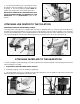
STARTING AND STOPPING THE LATHE
The on/off switch (A) Fig. 17 is located on the bracket (B) attached earlier to the rear of the headstock. To turn the
switch “ON”, move the switch (A) up to the “ON” position. To turn the switch “OFF”, move the toggle switch (A) down
to the “OFF” position.
LOCKING SWITCH IN THE “OFF” POSITION
IMPORTANT: When the machine is not in use, the switch should be locked in the “OFF” position to prevent
unauthorized use.
To lock, grasp the toggle (C) Fig. 18, and pull it out of the switch (A).When the safety toggle (C) Fig. 18 is removed, the
switch will not operate. However, should the safety toggle be removed while the wood lathe is operating, the switch
can be turned “OFF” once, but cannot be restarted without inserting the safety toggle (C) back into the switch.
OPERATING CONTROLS AND ADJUSTMENTS
Fig. 17
Fig. 18
A
B
A
C
SPINDLE SPEEDS
Depending on the position of the belt on the motor and spindle pulleys, the wood lathe is capable of providing speeds
of 500, 800, 1250, 1800, 2650, and 3700 RPM.
CHANGING SPINDLE SPEEDS
The wood lathe features a six-step motor pulley and spindle pulley to provide the different spindle speeds for particular
wood turning applications. To change speeds:
1. Disconnect machine from power source
.