(Model MM300) PART NO. 906119 - 06-15-02 Copyright © 2002 Delta Machinery To learn more about DELTA MACHINERY visit our website at: www.deltamachinery.com. For Parts, Service, Warranty or other Assistance, please call ESPAÑOL: PÁGINA 19 1-800-223-7278 (In Canada call 1-800-463-3582).
GENERAL SAFETY RULES Woodworking can be dangerous if safe and proper operating procedures are not followed. As with all machinery, there are certain hazards involved with the operation of the product. Using the machine with respect and caution will considerably lessen the possibility of personal injury. However, if normal safety precautions are overlooked or ignored, personal injury to the operator may result.
ADDITIONAL SAFETY RULES FOR HOLLOW CHISEL MORTISERS WARNING: FAILURE TO FOLLOW THESE RULES MAY RESULT IN SERIOUS PERSONAL INJURY. 1. DO NOT OPERATE THIS MACHINE until it is assembled and installed according to the instructions. 15. ALWAYS turn off the power before removing scrap pieces from the table. 2. OBTAIN ADVICE FROM YOUR SUPERVISOR, instructor, or another qualified person if you are not familiar with the operation of this machine. 16.
POWER CONNECTIONS A separate electrical circuit should be used for your machines. This circuit should not be less than #12 wire and should be protected with a 20 Amp time lag fuse. If an extension cord is used, use only 3-wire extension cords which have 3prong grounding type plugs and matching receptacle which will accept the machine’s plug.
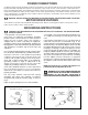
EXTENSION CORDS Use proper extension cords. Make sure your extension cord is in good condition and is a 3-wire extension cord which has a 3-prong grounding type plug and matching receptacle which will accept the machine’s plug. When using an extension cord, be sure to use one heavy enough to carry the current of the machine. An undersized cord will cause a drop in line voltage, resulting in loss of power and overheating. Fig. D, shows the correct gauge to use depending on the cord length.
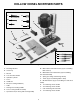
HOLLOW CHISEL MORTISER PARTS O L M P A N Q D C B E K F G I R S J H T U Fig.
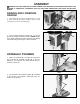
ASSEMBLY WARNING: FOR YOUR OWN SAFETY, DO NOT CONNECT THE MACHINE TO THE POWER SOURCE UNTIL THE MACHINE IS COMPLETELY ASSEMBLED AND YOU READ AND UNDERSTAND THE ENTIRE INSTRUCTION MANUAL. B RAISING AND LOWERING HANDLE A 1. Assemble hub of handle assembly (A) Fig. 3, to end of pinion shaft (B) and fasten handle to pinion shaft using special screw (C) and spring (D). D C Fig. 3 B 2. Raise mortising machine head (E) Fig. 4, to the up position by turning handle (A) clockwise.
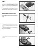
TABLE 1. Assemble the table (A) Fig. 7, to the base using the two M6x1x35mm flat head screws (B) and T-nuts (C). Insert the two screws (B) into the two holes (D) in table (A). Place the two T-nuts (C) into the slots (E) provided in the bottom of the base and tighten the two screws (B) into the two T-nuts (C) securely. E A D C B E 2. The table (A) Fig. 7, can be moved in or out by loosening the two screws (B), and re-positioning the table, and then tightening screws (B). Fig.
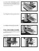
5. Insert bar of fence assembly (E) Fig. 11, through hole in column as shown. Tighten handle (C) against flat on fence bar to hold fence in position. NOTE: Handle (C) is spring-loaded and can be repositioned on the stud located underneath the handle by pulling out the handle and repositioning it on the stud. E C Fig. 11 6. Insert bar (F) Fig. 12, into hole on top of fence as shown, and tighten set screw (G) against flat on bar (F). F G Fig. 12 7. Assemble the holddown (H) Fig.
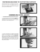
FASTENING MACHINE TO SUPPORTING SURFACE If during operation there is any tendency for the mortiser to tip over, slide or walk on the supporting surface, the base must be secured to the supporting surface with fasteners (not supplied), through the two holes (A) Fig. 16, located in the mortiser base. A A Fig. 16 ASSEMBLING CHISEL AND BIT 1. DISCONNECT MACHINE FROM POWER SOURCE. A 2. Insert bit (A) Fig. 20, into chisel (B).
4. Push bit (A) Fig. 23, up through chisel and into chuck (G) as far as it will go, and lock bit in chuck using chuck key supplied. G A Fig. 23 5. Loosen set screw (D) Fig. 24, and push chisel (B) up against bottom of bushing (E), as shown, and tighten set screw (D). This should provide the proper distance between the cutting lips of the bit and the points of the chisel. D E B Fig. 24 6. The flat portion of the bit should be adjusted to a minimum of 1/16" below the bottom of the chisel, as shown in Fig.
OPERATING CONTROLS AND ADJUSTMENTS ON-OFF SWITCH The switch (A) Fig. 26, is located on the side of the motor. To turn the machine “ON”, move the switch (A), up to the “ON” position. To turn the machine “OFF”, move the switch down to the “OFF” position. A Fig. 26 LOCKING SWITCH IN THE “OFF” POSITION When the tool is not in use, the switch should be locked in the “OFF” position to prevent unauthorized use. This can be done by grasping the switch toggle (B) Fig.
DEPTH STOP ROD C A depth stop rod (A) Fig. 29, is provided to limit the depth of the chisel (B). To adjust the depth stop rod (A), loosen screw (C) and lower head until the chisel (B) is at the desired depth. Lower depth stop rod (A) until it contacts base (D) and tighten screw (C). A B D Fig. 29 FENCE The fence (A) Fig. 30, can be moved in or out by loosening lever (B), sliding fence to the desired position and tightening lever (B).
SLIDING FIT BETWEEN HEAD AND COLUMN B A dovetail gib (A) Fig. 32, is provided on the rear of the head to insure a good sliding fit between the head and the column when the head is raised and lowered. Adjustment is made by loosening the two screws (B) and turning adjusting screws (C). Then tighten two screws (B). NOTE: Correct adjustment is when a good snug sliding fit is obtained without any side movement between the gib and the column.
USING AUXILIARY WOOD FENCE E A When mortising extra high workpieces (A) Fig. 35, an auxiliary fence (B) can be fastened to the fence (C) with wood screws (D) through the two holes in the fence. This provides additional support for the workpiece during the mortising operation. Note that the holddown (E) can be turned upside down to accommodate the extra height of the workpiece. B D C Fig. 35 ROTATING COLUMN 180 DEGREES The column (A) Fig.
USING BITS WITH EXTRA LONG SHANKS A C When using bits with extra long shanks, it will be necessary to remove the extension (A) Fig. 37. This can be accomplished by inserting screwdriver into center hole of motor end cap (B) Fig. 38, and into slot in end of armature shaft. Then using chuck key, unscrew and remove chuck (C) Fig. 37, and extension (A). Remove extension (A) from chuck (C) and replace chuck (C) on end of motor shaft. Fig. 37 B Fig.
NOTES 17
ACCESSORIES A complete line of accessories is available from your Delta Supplier, Porter-Cable • Delta Factory Service Centers, and Delta Authorized Service Stations. Please visit our Web Site www.deltamachinery.com for a catalog or for the name of your nearest supplier. WARNING: Since accessories other than those offered by Delta have not been tested with this product, use of such accessories could be hazardous. For safest operation, only Delta recommended accessories should be used with this product.