31-300 6" Belt/12" Disc Sanding Center Courroie de 152,4 mm (6 po)/Disque de 304,8 mm (12 po) Module de ponçage Banda de 152 mm (6") / disco de 304, 8 mm (12") Centro de lijado Instruction Manual Manuel d’utilisation Manual de instrucciones FRANÇAIS (21) ESPAÑOL (40) www.deltamachinery.
TABLE OF CONTENTS IMPORTANT SAFETY INSTRUCTIONS ....................2 SAFETY GUIDELINES - DEFINITIONS .....................2 GENERAL SAFETY RULES .......................................3 ADDITIONAL SPECIFIC SAFETY RULES ................4 FUNCTIONAL DESCRIPTION ...................................7 CARTON CONTENTS ...............................................7 ASSEMBLY .................................................................8 OPERATION ...............................................................
GENERAL SAFETY RULES Failure to follow these rules may result in serious personal injury. 1. 2. 3. 4. 5. 6. 7. 8. 9. 10. 11. 12. 13. 14. USE THE PROPER EXTENSION CORD. Make sure your extension cord is in good condition. When using an extension cord, be sure to use one heavy enough to carry the current your product will draw. An undersized cord will cause a drop in line voltage, resulting in loss of power and overheating.
ADDITIONAL SPECIFIC SAFETY RULES Failure to follow these rules may result in serious personal injury. 1. DO NOT OPERATE THIS MACHINE until it is completely assembled and installed according to the instructions. A machine incorrectly assembled can cause serious injury. 2. OBTAIN ADVICE from your supervisor, instructor, or another qualified person if you are not thoroughly familiar with the operation of this machine. Knowledge is safety. 3.
POWER CONNECTIONS A separate electrical circuit should be used for your machines. This circuit should not be less than #12 wire and should be protected with a time delay fuse. NOTE: Time delay fuses should be marked “D” in Canada and “T” in the US. If an extension cord is used, use only 3-wire extension cords which have 3-prong grounding type plugs and matching receptacle which will accept the machine’s plug.
3. 240 VOLT SINGLE PHASE OPERATION The motor supplied with your machine is a dual voltage, 120/240 volt motor. It is shipped readyto-run for 120 volt operation. However, it can be converted for 240 volt operation. A qualified electrician should do the conversion, or the machine can be taken to an Authorized Delta Service Center. When completed, the machine must conform to the National Electric Code and all local codes and ordinances.
FUNCTIONAL DESCRIPTION FOREWORD Delta Model 31-300 is an industrial/commercial duty 1-1/2 HP belt/disc sander. The induction-type, ball-bearing motor provides long-lasting, smooth performance. The Sanding Center can provide 3000 SFPM with the belt, and the disc will revolve at 2100 RPM. NOTICE: The manual cover illustrates the current production model. All other illustrations contained in the manual are representative only and may not depict the actual labeling or accessories included.
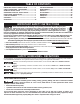
22 30 23 31 39 24 32 25 33 26 34 27 35 28 36 29 37 38 For stand assembly: For attaching the motor to the stand: 22. 23. 24. 25. 30. 31. 32. 33. 34. 35. 36. 37. 38. 39. 5/16-18 x 5/8"Carriage Bolt (32) 5/16" Lock Washer (32) 5/16" Flat Washer (32) 5/16"-18 Hex nut (32) For attaching the center to the stand 26. 27. 28. 29.
ASSEMBLING THE STAND 1. Use sixteen 5/8" carriage bolts, flat washers, lockwashers, and hex nuts to attach two short lower braces (A) Fig. 1 and two long lower braces (B) to the four legs (C). D C NOTE: Hand tighten the hex nuts for fufther adjustments. 2. Use the remaining carriage bolts, flat washers, lockwashers, and hex nuts to attach the top shelf (D) to the legs. A B NOTE: Hand tighten the hex nuts for future adjustments. 3. Make sure that the stand is on level ground.
INSTALLING THE DRIVE BELT AND THE BELT GUARD Disconnect the machine from the power source! 1. 2. 3. 4. 5. 6. 7. 8. 9. Place the belt (A) Fig. 4 on the sander drive pulley. Lift the motor and place the other end of the belt on the motor pulley (B) Fig.4. Lower the motor to tighten the belt. Check the pulleys for alignment. To adjust, loosen the set screw (E) Fig. 4 with a 3/16" hex wrench to move the motor pulley (B). Tighten the set screw. For an additional adjustment, loosen the nuts (D) Fig.
ATTACHING THE DISC TABLE Disconnect the machine from the power source! E C D A A B B Fig.9 1. 2. 3. 4. 5. 6. 7. A Fig. 11 Fig. 10 C C B Thread the disc table trunnion stud (A) Figs. 9 & 10 in the hole (B) Fig. 10 on the side of the machine. (This stud is listed as No. 15 in the carton contents). Tighten securely. Place the disc table trunnion clamp (C) Figs. 9 & 10 on the stud. Insert the two pins (D) in the two holes (E). Attach the washer, spring, and knob.
OPERATION OPERATIONAL CONTROLS AND ADJUSTMENTS A A A Fig. 16 Fig. 17 Fig. 18 STARTING AND STOPPING THE MACHINE Make sure that the switch is in the “OFF” position before plugging the cord into the outlet. Do not touch the plug’s metal prongs when unplugging or plugging in the cord. The on-off switch (A) Fig. 16 is located on the sander base. To turn the sander “ON”, move the switch to the up position. To turn the sander “OFF”, move the switch to the down position.
3. Rotate the belt (D) Fig. 21 by hand, and tighten or loosen the tracking knob (E) Figs. 20 and 21 until the tracking is correct. 4. Turn the tool on and off to check for proper tracking. If the belt is leading to one side or the other, very gently turn the tracking knob (E) Fig. 20 clockwise to move the belt to the right or counter-clockwise to move the belt to the left. 5. A final adjustment can be made with the motor running. THIS ADJUSTMENT SHOULD BE VERY SLIGHT. 6.
TILTING THE BELT SANDER TABLE Disconnect the machine from the power source. You can tilt the table (A) Fig. 25 down to 45 °. To tilt the table, loosen the lock handle (B). Note the degree of tilt on the pointer and scale. Stop (E) Fig. 26 can be positioned for 45° or 40° by turning the screw (F) to adjust the angle. NOTE: When tilting the table, rotate the stop (E) Fig. 26 out of the way. B C D A E F Fig. 25 Fig.
2. C Remove the top idler pulley cover (C) Figs. 30 and 31 when sanding in the horizontal position. For a long workpiece, lower the deflector plate (D) Fig. 30. For a short workpiece, raise the deflector plate (D) to deflect saw dust. A NOTE: With the sanding arm (A) in the horizontal position (Fig. 30), use the table (E) or the accessory backstop to support the work. E B Fig. 31 ADJUSTING THE DISC TABLE Disconnect the machine from the power source. E F A B Fig. 32 Fig. 33 1.
ADJUSTING THE MITER GAUGE SLOT Disconnect the machine from the power source. 1. 2. 3. 4. With the table (A) Fig. 35 positioned 90° to the disc, place a square (B) in the miter gauge slot with the blade of the square touching the sanding disc. Use a pencil to mark the place where the blade contacts the disc. (Fig. 35). Rotate the disc 180.° Use a square to check the distance between the miter gauge slot and the mark on the disc made in STEP 3.
REPLACING SANDING DISC Disconnect the machine from the power source. See “ATTACHING THE SANDING DISC” section in this manual. MACHINE USE A A B Fig.41 Fig.42 SURFACING OR EDGE SANDING WITH SANDING BELT When surfacing sanding (Fig. 41) or edge sanding (Fig. 42), place the sanding arm in the horizontal position. Use the table (A) to keep the workpiece in place. Hold the workpiece firmly and keep your fingers away from the sanding belt. Place the end of the workpiece against the table.
B C A Fig.46 Fig.45 END SANDING WITH THE DISC When sanding the ends of narrow workpieces, use the sanding disc and an accessory miter gauge (A) Fig. 45. Move the work from the center to the left side (downward) of the sanding disc. Always sand on the left SIDE (downward ROTATION side) of the sanding disc (Fig. 45). Sanding on the right SIDE (upward ROTATION side) of the sanding disc could cause the workpiece to fly up, which could be hazardous. Position the edge of the table (C) Fig.
SERVICE REPLACEMENT PARTS Use only identical replacement parts. For a parts list or to order parts, visit our website at servicenet.deltamachinery.com. You can also order parts from your nearest factory-owned branch, or by calling our Customer Care Center at 1-800-223-7278 to receive personalized support from highly-trained technicians. FREE WARNING LABEL REPLACEMENT If your warning labels become illegible or are missing, call 1-800-223-7278 for a free replacement.
ACCESSORIES A complete line of accessories is available from your Delta Supplier, Porter-Cable • Delta Factory Service Centers, and Delta Authorized Service Stations. Please visit our Web Site www.deltamachinery.com for a catalog or for the name of your nearest supplier. Since accessories other than those offered by Delta have not been tested with this product, use of such accessories could be hazardous. For safest operation, only Delta recommended accessories should be used with this product.
LES INSTRUCTIONS IMPORTANTES DE SURETE Lire et comprendre toutes instructions d'avertissements et opération avant d'utiliser n'importe quel outil ou n'importe quel équipement. En utilisant les outils ou l'équipement, les précautions de sûreté fondamentales toujours devraient être suivies pour réduire le risque de blessure personnelle. L'opération déplacée, l'entretien ou la modification d'outils ou d'équipement ont pour résultat la blessure sérieux et les dommages de propriété.
RÈGLES DE SÉCURITÉ GÉNÉRALES L’inobservation de ces règles peut conduire à des blessures graves. 1. POUR SA SÉCURITÉ PERSONNELLE, LIRE LA NOTICE D’UTILISATION, AVANT DE METTRE LA MACHINE EN MARCHE, et pour aussi apprendre l’application et les limites de la machine ainsi que les risques qui lui sont particuliers ainsi, les possibilités d’accident et de blessures seront beaucoup réduites. 2. PORTEZ DES DISPOSITIFS DE PROTECTION DES YEUX ET DE L'OUÏE. UTILISEZ TOUJOURS DES LUNETTES DE SÉCURITÉ.
RÈGLES SPÉCIFIQUES ADDITIONNELLES DE SÛRETÉ L’inobservation de ces règles peut conduire à des blessures graves. 1. NE PAS FAIRE FONCTIONNER CET APPAREIL avant qu’il ne soit entièrement assemblé et installé conformément à ces directives. Un appareil mal assemblé peut provoquer des blessures graves. 2. D E M A N D E R C O N S E I L à u n s u p e r v i s e u r, instructeur, ou toute autre personne qualifiée si l’on ne maîtrise pas parfaitement l’utilisation de cet appareil.
RACCORDEMENTS ÉLECTRIQUES Un circuit électrique séparé doit être utilisé pour les machines. Ce circuit doit utiliser un câble de calibre 12 au minimum et doit être protégé par un fusible temporisé. REMARQUE : les fusibles temporisés devraient avoir l’inscription « D » au Canada et « T » aux É.-U. Si on utilise un cordon prolongateur, ce cordon doit être à trois fils, avoir unefiche à trois broches et une prise de courant à trois cavités, mise à la terre qui correspond à la fiche de la machine.
3. FONCTIONNEMENT MONOPHASÉ À 240 VOLTS BOÎTE DE SORTIE MISE À LA TERRE LAMES CONDUCTRICES Le moteur fourni avec la machine est un moteur bitension de 120/240 volts. Il est livré, prêt à fonctionner, sous tension de 120 volts. Toutefois, il peut être converti au fonctionnement sous 240 volts. Un électricien professionnel devrait effectuer la conversion ou utiliser les services d’un centre de réparations agréé Delta.
DESCRIPTION FONCTIONNELLE AVANT-PROPOS Le modèle Delta 31-300 est une ponceuse industrielle/commerciale de 1-1/2 HP à courroie/à disque. Le moteur à induction avec roulement à billes assure un rendement durable sans à-coups. Le module de ponçage peut fournir 3 000 pieds linéaires (914,4 m) par minute avec la bande et le disque tourne à un régime de 2 100 tr/min. REMARQUE : La image sur la couverture illustre le modèle de production actuel.
22 30 23 31 39 24 32 25 33 26 34 27 35 28 36 29 37 38 Fixation du moteur au support de moteur : 30. (2) rondelles plates de 1/2 po 31. (2) contre-écrous de 1/2 po 32. (2) boulons à tête hexagonale de 1/2-13 x 3/4 po 33. (2) rondelles de blocage de 5/16 po 34. (2) rondelles plates de 5/16 po 35. (2) écrous à oreille de 5/16 po 36. (2) boulons de carrosserie de 5/16 po-18 x 1 po 37. Pointeur 38. Vis à tête ronde no 10-32 39. Module de ponçage Pour l'assemblage du socle 22.
ASSEMBLAGE DU SOCLE 1. Fixer les deux entretoises inférieures courtes (A), fig. 1, ainsi que les deux autres entretoises inférieures longues (B) aux quatre pattes (C), à l'aide des 16 boulons de carrosserie de 5/8 po, rondelles plates, rondelles de blocage et des écrous hexagonaux. REMARQUE : serrer manuellement les écrous hexagonaux en vue d'un réglage ultérieur. 2.
INSTALLATION D'UNE COURROIE D'ENTRAÎNEMENT ET UN PROTÈGE-COURROIE Debrancher l'appareil de la source d'alimentation . 1. 2. 3. 4. 5. 6. 7. 8. 9. Placer la courroie (A) fig. 4 sur la poulie d’entraînement de la ponceuse. Soulever le moteur et placer l’autre extrémité de la courroie autour de la poulie moteur (B) fig. 4. Abaisser le moteur pour serrer la courroie. Vérifier l’alignement des poulies. Pour ajuster, desserrer la vis de calage (E) fig.
FIXATION DE LA TABLE POUR PONCEUSE À DISQUE Debrancher l'appareil de la source d'alimentation . E C D A A B B Fig.9 1. 2. 3. 4. 5. 6. 7. B Fig. 11 Fig. 10 C D B Visser le goujon de tourillon (A), figs. 9 & 10, de la table pour ponceuse à disque dans le trou (B) Fig. 10 pratiqué sur le côté de l'appareil. (Ce goujon est énuméré comme No 15 dans les contenus de boîte). Bien serrer.
FONCTIONNEMENT L'OPERATION CONTROLE DE LE ET LES AJUSTEMENTS A A A Fig. 16 Fig. 17 Fig. 18 MARCHE ET ARRÊT DE L'APPAREIL S’assurer que l’interrupteur se trouve sur la position d’arrêt avant de brancher le cordon d’alimentation dans la prise. Ne pas toucher aux lames métalliques de la fiche lors du branchement ou débranchement du cordon. L'interrupteur marche/arrêt (A), fig. 16, est situé sur le socle de la ponceuse. Pour mettre la ponceuse sous tension, déplacer l'interrupteur à la position haute.
3. Tourner manuellement la bande abrasive (D), fig. 21, puis serrer ou desserrer le bouton de centrage (E), fig. 20 et 21, de sorte que le centrage de la bande soit adéquat. 4. Mettre en marche et éteindre l'outil pour s'assurer du bon centrage. Si la bande tend vers un côté ou l'autre, tourner très doucement le bouton de centrage (E), fig. 20, en sens horaire pour déplacer la bande à droite ou en sens antihoraire pour la déplacer à gauche. 5. 6.
INCLINATION DE LA TABLE DE PONCEUSE À COURROIE Debrancher l'appareil de la source d'alimentation . La table (A) peut être incliné à un angle descendant de 45 degrés (fig. 25). Pour incliner la table, desserrer la poignée de verrouillage (B), incliner la table à l'angle voulu, puis serrer la poignée (B). Le degré d'inclination est noté sur le pointeur et l'échelle. Arrêter (E) fig. 26 peut être disposé pour 45 ou 40 degrés en tournant la vis (F) ajuster l'angle.
2. C Il est possible d'enlever le couvercle supérieur de la poulie tendeur (C), fig. 30 et 31, pour dégager la pièce durant le ponçage à la position horizontale. Pour une pièce longue, baisser la plaque de déviation (D) pour dégager la pièce. Monter la plaque de déviation (D) pour dévier la sciure durant la ponçage d'une petite pièce. A E REMARQUE : le bras de ponçage (A) étant à l'horizontal (fig. 31), utiliser la table (E) ou la butée accessoire pour soutenir la pièce. B Fig.
RÉGLAGE DU PARALLÉLISME DE LA RAINURE DU GUIDE D'ONGLETS Debrancher l'appareil de la source d'alimentation . 1. La table (A), fig. 35, étant positionnée à un angle de 90 degrés par rapport au disque, insérer une équerre (B) dans la rainure du guide d'onglets de sorte que ° la lame de l'équerre entre en contact avec le disque abrasif. 2. Marquer le disque au crayon au point de contact de la lame. (fig. 35). 3. Tourner le disque à l'autre extrémité de la table.
REMPLACEMENT DU DISQUE ABRASIF Debrancher l'appareil de la source d'alimentation . Consulter la rubrique « FIXATION DU DISQUE ABRASIF » du présent mode d'emploi. SURFAÇAGE OU PONÇAGE DE CHANT AVEC LA BANDE ABRASIVE MACHINE USE A A B Fig.41 Fig.42 APPARAÎTRE OU APPROCHER PONÇAGE AVEC LA CEINTURE DE PONÇAGE Pour le surfaçage (fig. 44) ou le ponçage de chant (fig. 45), mettre le bras de ponçage à l'horizontal et utiliser la table (A), fig. 44 et fig. 45, pour maintenir la pièce en place.
B C A Fig.46 Fig.45 PONÇAGE D'EXTREMITE AVEC LE DISQUE Lors du ponçage des extrémités de pièces étroites, utiliser le disque abrasif et un guide d'onglets accessoire (A) fig. 45. Déplacer la pièce du centre vers le côté gauche (côté descendant) du disque abrasif. Toujours poncedr du cote gauche (cote de rotation descendante) du disque du disque abrasif (fig. 45).
SERVICE PIÈCES DE RECHANGE Utiliser seulement des pièces de rechange identiques. Pour obtenir une liste des pièces de rechange ou pour en commander, consulter notre site Web au servicenet.deltamachinery.com. Commander aussi des pièces auprès d’une succursale d’usine ou composer le 1-800-223-7278 pour le service à la clientèle et recevoir ainsi une assistance personnalisée de techniciens bien formés.
ACCESSOIRIES Une ligne complète des accessoires est fournie des centres commerciaux d'usine de par votre de Porter-Cable•Delta fournisseur, de Porter-Cable•Delta, et des stations service autorisées par Porter-Cable. Veuillez visiter notre site Web www.deltamachinery.com pour un catalogue ou pour le nom de votre fournisseur plus proche. Depuis des accessoires autre que ceux offertspar Porter-Cable•Delta n'ont pas été testés avec ce produit, utilisation de tels accessoires a pu être dangereux.
INSTRUCCIONES DE SEGURIDAD IMPORTANTES Lea y entienda todas advertencias y las instrucciones operadoras antes de utilizar cualquier instrumento o el equipo. Cuando se usa instrumentos o equipo, las precauciones básicas de la seguridad siempre se deben seguir para reducir el riesgo de la herida personal. La operación impropia, la conservación o la modificación de instrumentos o equipo podrían tener como resultado el daño grave de la herida y la propiedad.
NORMAS GENERALES DE SEGURIDAD Si no se siguen estas normas, el resultado podría ser lesiones graves. 1. 2. 3. 4. 5. 6. 7. 8. 9. 10. 11. 12. 13. 14. PARA SU PROPIA SEGURIDAD, LEA EL MANUAL DE INSTRUCCIONES ANTES DE UTILIZAR LA MÁQUINA. Al aprender la aplicación, las limitaciones y los peligros específicos de la máquina, se minimizará enormemente la posibilidad de accidentes y lesiones. USE PROTECCIÓN DE LOS OJOS Y DE LA AUDICIÓN. USE SIEMPRE ANTEOJOS DE SEGURIDAD.
NORMAS ESPECÍFICAS ADICIONALES DE SEGURIDAD Si no se siguen estas normas, el resultado podría ser lesiones personales graves. 1. NO OPERE ESTA MÁQUINA hasta que no esté armada e instalada completamente, según las instrucciones. Una máquina montada de manera incorrecta puede provocar lesiones graves. 2. SOLICITE EL ASESORAMIENTO de su supervisor, su instructor o alguna persona calificada si no está familiarizado con el funcionamiento de esta máquina. El conocimiento garantiza la seguridad. 3.
CONEXIONES A LA FUENTE DE ALIMENTACIÓN Debe utilizarse un circuito eléctrico independiente para las máquinas. Este circuito no debe ser menor a un cable Nº 12 y debe estar protegido con un fusible de acción retardada. NOTA: Los fusibles de acción retardada deben estar marcados “D” en Canadá y “T” en EE.UU.
3. OPERACIÓN DE UNA SOLA FASE CON 240 VOLTIOS El motor provisto con su máquina es de doble voltaje, es decir de 120/140 voltios. Viene listo para su funcionamiento en operaciones de 120 voltios. Sin embargo, se puede convertir para operaciones de 240 voltios. CAJA TOMACORRIENTE CONECTADA A TIERRA La conversión debe ser realizada por un electricista calificado, o se puede llevar la máquina a un centro de mantenimiento autorizado Delta.
DESCRIPCIÓN FUNCIONAL PROLOGO El modelo Delta 31-300 es una lijadora de banda/disco de 1-1/2 HP para uso industrial o comercial. El motor con cojinetes de bolas y sistema de inducción brinda un rendimiento duradero y uniforme. El centro de lijado puede brindar 3000 SFPM con la banda, y el disco gira a 2100 RPM. NOTA: El cuadro en la cubierta ilustra el modelo actual de la producción.
22 30 23 31 39 24 32 25 33 26 34 27 35 28 36 29 37 38 Para el montaje de la base: 21. Perno de soporte de 5/16-18 x 5/8" (32) 22. Arandela de bloqueo de 5/16" (32) 23. Arandela plana de 5/16" (32) 24. Tuerca hexagonal de 5/16"-18 (32) 25. 26. 27. 28. Para acoplar el motor a la base: 29. Arandela plana de 1/2" (2) 30. Tuerca de seguridad de 1/2" (2) 31. Perno de cabeza hexagonal de 1/2-13 x 3/4" (2) 32. Arandela de bloqueo de 5/16" (2) 33. Arandela plana de 5/16" (2) 34.
MONTAJE DE LA BASE 1. Ajuste los dos soportes inferiores cortos (A) Fig. 1, y los otros dos soportes inferiores largos (B) a las cuatro patas (C) utilizando los dieciséis pernos de soporte de 5/8", arandelas planas, arandelas de bloqueo y tuercas hexagonales. NOTA: Ajuste manualmente las tuercas hexagonales para facilitar los ajustes futuros. 2. Ajuste el estante superior (D) a las patas utilizando los restantes pernos de soporte, arandelas planas, arandelas de bloqueo y tuercas hexagonales.
INSTALACIÓN DE LA CORREA IMPULSORA Y EL GUARDACORREA Desconecte la máquina de la fuente de alimentacion. 1. 2. 3. 4. 5. 6. 7. 8. 9. Coloque la correa (A) Fig. 4 en la polea impulsora de la lijadora. Levante el motor y coloque el otro extremo de la correa en la polea del motor (B) Fig.4. Baje el motor para ajustar la correa. Controle las poleas para verificar la alineación. Para ajustar, afloje el tornillo de sujeción (E) Fig. 4 con una llave hexagonal de 4,8 mm (3/16") para mover la polea del motor (B).
ACOPLE DEL BANCO PARA DISCO Desconecte la máquina de la fuente de alimentacion. E C D A A B B Fig.9 1. 2. 3. 4. 5. 6. 7. B Fig. 11 Fig. 10 C D B Enrosque el espárrago del soporte giratorio del banco para disco (A) Figs. 9 & 10 en el orificio (B) Fig. 10 que se encuentra al costado de la máquina. (Este espárrago se lista como No. 15 en el contenido del cartón). Ajuste bien. Coloque la abrazadera de soporte giratorio del banco para disco (C) Figs.
OPERACIÓN CONTROLES Y AJUSTES OPERACIONALES A A A Fig. 16 Fig. 17 Fig. 18 ARRANCANDO Y DETENIENDO LA HERRIMENTEA Asegúrese de que el interruptor esté en la posición de “APAGADO” (OFF) antes de enchufar el cable de alimentación en el tomacorriente. No toque las patas de metal del enchufe al enchufar o desenchufar el cable. The on-off switch (A) Fig. 16 is located on the sander base. To turn the sander “ON”, move the switch to the up position.
3. Gire la banda (D) Fig. 21 manualmente y ajuste o afloje la perilla de desplazamiento (E) Figs. 20 y 21 hasta que la banda se desplace correctamente. 4. Encienda y apague la herramienta para verificar el desplazamiento adecuado. Si la banda se desplaza hacia un lado o el otro, gire suavemente la perilla de desplazamiento (E) Fig. 20 en sentido de las agujas del reloj para mover la banda hacia la derecha, o en sentido contrario a las agujas del reloj para mover la banda hacia la izquierda. 5.
INCLINACIÓN DEL BANCO PARA LIJADORA DE BANDA Desconecte la máquina de la fuente de alimentacion. El banco (A) Fig. 25puede inclinarse 45 grados hacia abajo. Para inclinar el banco, afloje el mango de bloqueo (B), incline el banco hacia el ángulo deseado y ajuste el mango de bloqueo (B). El grado de inclinación se indica en el indicador y la escala. Pare (E) Fig. 26 pueden ser posicionados para 45 o 40 grados girando el tornillo (F) ajustar el ángulo.
2. C La cubierta superior de la polea intermedia (C) Figs. 30 y 31 puede retirarse para despejar la pieza de trabajo al lijar en posición horizontal. En el caso de una pieza de trabajo larga, baje la placa deflectora (D) para despejar la pieza de trabajo. Levante la placa deflectora (D) para desviar el aserrín de madera al lijar una pieza de trabajo corta. A E NOTA: Con el brazo de lijado (A) en posición horizontal (Fig.
AJUSTE DE LA RANURA DEL CALIBRADOR DE INGLETE Desconecte la máquina de la fuente de alimentacion. 1. Con el banco (A) Fig. 35 ubicado a 90 grados del disco, coloque una escuadra (B) en la ranura del calibrador de inglete de manera que el filo de la escuadra toque el disco de lijar. 2. Utilice un lápiz para hacer una marca en el disco en el lugar donde el filo lo toca. (Fig. 35). 3. Gire el disco hacia el otro extremo del banco.
REEMPLAZO DEL DISCO DE LIJAR Desconecte la máquina de la fuente de alimentacion. Consulte la sección "ACOPLE DEL DISCO DE LIJAR" de este manual. UTILIZAR LA MAQUINA A A B Fig.41 Fig.42 LIJADO DE SUPERFICIES O BORDES CON LA BANDA DE LIJADO Al lijar superficies (Fig. 41) o bordes (Fig. 42), coloque el brazo de lijado en posición horizontal y utilice el banco (A) Fig. 44 y Fig. 45 para mantener la pieza de trabajo en su lugar.
B C A Fig.45 Fig.46 LIJADO DE TERMINACIONES CON EL DISCO Al lijar las terminaciones de piezas de trabajo angostas, utilice el disco de lijar y un calibrador de inglete accesorio (A) Fig. 45. Mueva la pieza de trabajo desde el centro hacia el lado izquierdo (descendente) del disco de lijar. Lije siempre sobre sobre el lado izquierdo (lado de giro descendente) del disco de lijar (fig. 45).
SERVICIO PIEZAS DE REPUESTO Utilice sólo piezas de repuesto idénticas. Para obtener una lista de piezas o para solicitar piezas, visite nuestro sitio web en servicenet.deltamachinery.com. También puede solicitar piezas en nuestro centro más cercano, o llamando a nuestro Centro de atención al cliente al 1-800-223-7278 para obtener asistencia personalizada de nuestros técnicos capacitados.
ACCESORIOS Una línea completa de accesorios está disponible de su surtidor de Porter-Cable • Delta, centros de servicio de la fábrica de Porter-Cable • Delta, y estaciones autorizadas delta. Visite por favor nuestro Web site www.deltamachinery. com para un catálogo o para el nombre de su surtidor más cercano. Puesto que los accesorios con excepción de ésos ofrecidos por Delta no se han probado con este producto, el uso de tales accesorios podría ser peligroso.
The following are trademarks for one or more Porter-Cable and Delta products: Les marques suivantes sont des marques de commerce se rapportant à un ou plusieurs produits Porter-Cable ou Delta : Las siguientes son marcas comerciales para uno o más productos de Porter-Cable y Delta: 2 BY 4®, 890™, Air America®, AIRBOSS™, Auto-Set®, B.O.S.S.