(Model MS210) U.S. Patent #5,347,902 PART NO. 905590 - 11-26-03 Copyright © 2003 Delta Machinery To learn more about DELTA MACHINERY visit our website at: www.deltamachinery.com. For Parts, Service, Warranty or other Assistance, please call ESPAÑOL: PÁGINA 19 1-800-223-7278 (In Canada call 1-800-463-3582).
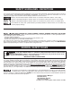
SAFETY GUIDELINES - DEFINITIONS This manual contains information that is important for you to know and understand. This information relates to protecting YOUR SAFETY and PREVENTING EQUIPMENT PROBLEMS. To help you recognize this information, we use the symbols to the right. Please read the manual and pay attention to these sections. Indicates an imminently hazardous situation which, if not avoided, will result in death or serious injury.
FAILURE TO FOLLOW THESE RULES MAY RESULT IN SERIOUS PERSONAL INJURY. 1. 2. 3. 4. 5. 6. 7. 8. 9. 10. 11. 12. FOR YOUR OWN SAFETY, READ THE INSTRUCTION MANUAL BEFORE OPERATING THE MACHINE. Learning the machine’s application, limitations, and specific hazards will greatly minimize the possibility of accidents and injury. USE CERTIFIED SAFETY EQUIPMENT. Eye protection equipment should comply with ANSI Z87.1 standards, hearing equipment should comply with ANSI S3.
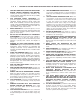
ADDITIONAL SAFETY RULES FOR MITER SAWS FAILURE TO FOLLOW THESE RULES MAY RESULT IN SERIOUS INJURY. 1. 2. 3. 4. 5. 6. 7. 8. 9. 10. 11. 12. 13. 14. 15. 16. 17. 18. DO NOT OPERATE THIS MACHINE until it is completely assembled and installed according to the instructions. A machine incorrectly assembled can cause serious injury. OBTAIN ADVICE from your supervisor, instructor, or another qualified person if you are not thoroughly familiar with the operation of this machine. Knowledge is safety.
POWER CONNECTIONS A separate electrical circuit should be used for your machines. This circuit should not be less than #12 wire and should be protected with a 20 Amp time lag fuse. If an extension cord is used, use only 3-wire extension cords which have 3prong grounding type plugs and matching receptacle which will accept the machine’s plug.
EXTENSION CORDS Use proper extension cords. Make sure your extension cord is in good condition and is a 3-wire extension cord which has a 3-prong grounding type plug and matching receptacle which will accept the machine’s plug. When using an extension cord, be sure to use one heavy enough to carry the current of the machine. An undersized cord will cause a drop in line voltage, resulting in loss of power and overheating. Fig. C shows the correct gauge to use depending on the cord length.
NOTICE: The manual cover photo illustrates the current production model. All other illustrations are representative only and may not depict the actual color, labeling, or accessories, and are intended to illustrate technique only. For your own safety, do not connect the miter saw to the power source until the machine is completely assembled and you read and understand the entire manual. ASSEMBLY ATTACHING TABLE LOCK HANDLE Thread table lock handle (A) Fig. 2 into the threaded hole (B) of the arm bracket.
FASTENING MACHINE TO SUPPORTING SURFACE Before operating your miter saw, make sure that it is firmly mounted to a sturdy workbench or other supporting surface. Four holes are provided, two of which are shown at (A) Fig. 7. When frequently moving the saw from place to place, we suggest that the saw be mounted to a 3/4" piece of plywood. The saw can then be easily moved from place to place and the plywood clamped to the supporting surface using “C” clamps. A Fig.
A B Fig. 11 Fig. 10 STARTING AND STOPPING MACHINE To start the machine, depress switch trigger (A) Fig. 10. To stop the machine, release the switch trigger. This miter saw is equipped with an automatic electric blade brake. As soon as the switch trigger (A) Fig. 10 is released, the electric brake is activated and stops the blade in seconds. A turning saw blade can be hazardous. After completing the cut, release the switch trigger (A) Fig. 10 to activate the blade brake.
B A ADJUSTING POINTER If it becomes necessary to adjust the pointer (A) Fig. 14, loosen screw (B), adjust the pointer and tighten screw (B). LOCKING CUTTERHEAD IN THE DOWN POSITION When transporting the miter saw, the cutterhead should always be locked in the down position. Lower the cutting arm (A) Fig. 15, and push in plunger (B) until other end of plunger (B) engages with hole in cutting arm. Fig. 14 A B IMPORTANT: Carrying the machine by the switch handle will cause misalignment.
ADJUSTING FENCE 90 DEGREES TO BLADE If the fence (A) Fig. 19 is removed from the saw, re-adjust it so that it is 90 degrees to the blade when the fence is replaced. Disconnect machine from power source. 1. Place one end of the square (B) Fig. 19 against the fence (A) and the other end against the blade. 2. If an adjustment is necessary, loosen the two screws (C) Fig. 20, and adjust fence 90 degrees to the blade. 3. Tighten the two screws (C). C C A B Fig. 20 Fig.
AUXILIARY WOOD FENCE When performing multiple or repetitive cut-off operations that result in small cut-off pieces, one inch or less, it is possible for the saw blade to catch the cut-off pieces and project them out of the machine or into the blade guard and housing, possibly causing damage or injury. To limit the possibility of personal injury or blade guard damage, an auxiliary wood fence can be mounted to your saw. Holes are provided in the fence to attach an auxiliary fence (A) Fig. 23.
CUTTING ALUMINUM Aluminum extrusions, such as used for making aluminum screens and storm windows, can be cut with your miter saw. To cut aluminum extrusions, or other sections that can be cut with a saw blade and are within the capacity of the machine, position the material so that the blade cuts through the smallest cross-section (Fig. 25). The wrong way to cut aluminum angles is illustrated in Fig. 26. Be sure to apply a stick wax to the blade before cutting aluminum stock.
FILLER BLOCK FOR CROWN MOULDING IF JOINT IS TO HAVE MITERED CORNER FIT OR COPE CUT FILLER BLOCK FOR CROWN MOULDING IF JOINT IS TO HAVE MITERED CORNER FIT OR COPE CUT Fig. 30 Fig. 31 2. When a large number of repetitive cuts of crown moulding are required, we suggest the use of filler blocks, as shown in Fig. 30 through Fig. 33.
D C E B Fig. 36A Fig. 36B 6. Fig. 36A illustrates the two outside corner pieces (B) and (E) 7. Fig. 36B illustrates the two inside corner pieces (C), and (D). MAINTENANCE CHANGING THE BLADE Use only cross-cutting saw blades. Use carbide-tipped blades with a negative hook angle. Do not use blades with deep gullets that can deflect and contact the guard. Use only 10" diameter saw blades which are rated for 5200 rpm or higher and have 5/8" diameter arbor holes. Disconnect machine from power source.
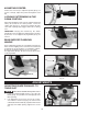
1. 2. 3. 4. 5. 6. Remove screw (A) Fig. 37, and rotate cover (B) to the rear as shown in Fig. 38. To remove the saw blade, insert hex wrench (C) Fig. 39 into the hex hole located in the rear end of the motor shaft, to keep the shaft from turning. Use wrench (D) Fig. 40 to loosen arbor screw (E) by turning it clockwise. Remove arbor screw (E) Fig. 40, outside blade flange (F) and saw blade (G) from saw arbor. Place new blade on arbor. MAKE CERTAIN TEETH OF SAW BLADE ARE POINTING DOWN AT THE FRONT.
ACCESSORIES A complete line of accessories is available from your Delta Supplier, Porter-Cable • Delta Factory Service Centers, and Delta Authorized Service Stations. Please visit our Web Site www.deltamachinery.com for a catalog or for the name of your nearest supplier. Since accessories other than those offered by Delta have not been tested with this product, use of such accessories could be hazardous. For safest operation, only Delta recommended accessories should be used with this product.
NOTES 18
PORTER-CABLE • DELTA SERVICE CENTERS (CENTROS DE SERVICIO DE PORTER-CABLE • DELTA) Parts and Repair Service for Porter-Cable • Delta Machinery are Available at These Locations (Obtenga Refaccion de Partes o Servicio para su Herramienta en los Siguientes Centros de Porter-Cable • Delta) ARIZONA Tempe 85282 (Phoenix) 2400 West Southern Avenue Suite 105 Phone: (602) 437-1200 Fax: (602) 437-2200 CALIFORNIA Ontario 91761 (Los Angeles) 3949A East Guasti Road Phone: (909) 390-5555 Fax: (909) 390-5554 San Leandro