
User manual


Revision October 2006, 2006PDD23000013 7-1
Chapter 7 Troubleshooting
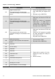
7.1 LED Displays
Two LEDs, SP and NET LED, are used to monitor the CME-PD01 communication status.
NET LED
State Indication Corrective Actions
LED is off No power
1. Verify that the power supply of CME-PD01.
2. Check whether the power supply is
connected and that power is applied to the
CME-PD01 through the connector.
Rapid Flashing
Red LED
Invalid PROFIBUS address
set via switch
Check whether the switch value is valid, valid
value of slave is within 1-125. Set the valid value
and re-power
Flashing Red
LED
1. Communication link to
PROFIBUS, but No
cyclical data exchanged
2. Extended user
parameter error
Parameters are sent by master (from GSD file).
For example, if d_state is set to 1, ensure the data
in Data Output 1 ~ Data Output [ dout_len-1] are
continuous addresses. Otherwise, CME-PD01 will
not be able to pass the Parameterization check.
Red LED
No connection to
PROFIBUS
1. Verify that network installation is OK.
2. Verify that PLC is working.
3. Verify that switch address setting is correct.
Flashing
Green LED
“Master” is in “Stop” mode,
cyclical process data
exchange is in progress,
but setting is invalid
(control word = 0)
Set PLC to RUN mode, and send the control
command to CME-PD01.
Green LED
Cyclic data is exchanging
and working