
User manual


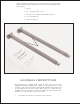

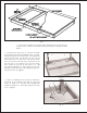
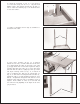


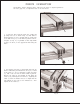

Fig. 17
Fig. 18 Fig. 19
16. Figure 19 illustrates the switch and nipple (W)
assembled to the switch adapter (X). The switch adapter
will be fastened to the front rail (A) and guide tube
through holes (Y) in the front rail af ter the guide tube is
fastened to the front rail (A).
15. Assemble the switch and nipple (W) Fig. 18, to switch
adapter for Unisaws (X) supplied with your T -Square fence.
14. If you are assembling the T -Square
fi
fence to a Delt a
Unisaw
fi
that has the on-of f switch (W) Fig. 17, suspended
from the bottom of the saw t able, as shown, remove the
switch and nipple (W) from the bottom of the saw t able.
13. Af ter the holes have been drilled in the edge of the front and rear extension
table board, fasten both front and rear rail to t able using the 1-1/2 flat head
Phillip s screws (T) Fig. 16, 1-1/4 O.D. flat washers (U) and hex nut s (V).
Fig. 16
T
T
U
V
W
Z
X
W
Y
X
A
W