
User's Manual

Warning
Always read this instruction sheet thoroughly before using DVP EH digital I/O extension unit.
This is an OPEN TYPE extension unit. The extension unit should be kept in an enclosure away from airborne, dust,
high humidity, electric shock risk and vibration. Also, it is equipped with protective methods such as special tools or
keys to open the enclosure, so as to avoid the hazard to users and damage the extension unit.
DO NOT connect AC main circuit power supply to any of the input/output terminals, as it will damage the extension
unit. Check all the wiring prior to power up. DO NOT touch terminals when power on.
Introduction
Thank you for choosing Delta DVP-EH series PLC. The main processing units offer 8 ~ 48 points and the
maximum input/output can be extended up to 256 points.
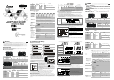
Product Profile and Outline
1
3
4
3
5
5 2
7
7
2
1
5
5
3
3
4
7
7
Dimension (mm)
Model
Length Width Height
DVP08HM11N 90 40 82
DVP16HM11N 90 55 82
DVP08HN11R/T 90 40 82
DVP16HP11R/T 90 55 82
3
4
2
6
6
6
7
7
3
3
8
9
1
10
11
Dimension (mm)
Model
Length Width Height
DVP32HN00R/T 90 143.5 82.2
DVP32HP00R/T 90 143.5 82.2
DVP48HP00R/T 90 174 82.2
1. Power, low voltage indicators 5. Extension wiring 9. Cover
2. I/O terminals 6. Extension port cover 10. Input indicators
3. DIN rail clip 7. Direct mounting holes 11. Output indicators
4. DIN rail 8. Model name
DVP EH Series Model
Input unit Output unit
Model Power
Points
Type Points
Type
DVP08HM11N 8 0
DVP16HM11N 16 0
N/A
DVP08HN11R 0 8
DVP08HP11R 4 4
DVP16HP11R 8 8
Relay: 250V AC/30V DC 2A/1point
DVP08HN11T 0 8
DVP08HP11T 4 4
DVP16HP11T
24V DC
8
DC Type
Sink/Source
8
Transistor: 5 ~ 30V DC 0.3A/1point at 40°C
EN
G
LISH
Specifications
Electrical Specification
Model
Item
08HM11N
16HM11N
08HN11R/T
08HP11R/T
16HP11R/T
32HN00R/T 32HP00R/T 48HP00R/T
Power supply voltage 24V DC (20.4 ~ 28.8V DC) (-15% ~ 20%) 100~240V AC (-15%~10%), 50/60Hz ± 5%
Power consumption 1W/1.5W
1.5W 1.5W 2W 30VA 30VA 30VA
24V DC supply current
NA NA NA NA NA 500mA 500mA
Power protection 24V DC output with short-circuit protection
Voltage withstand 1,500V AC (Primary-secondary), 1,500V AC (Primary-PE), 500V AC (Secondary-PE)
Insulation resistance > 5 MΩ at 500V DC (Between all input/output and earth)
Noise immunity
ESD: 8KV Air Discharge, EFT: Power Line: 2KV, Digital I/O: 1KV, Analog &
Communication I/O: 250V,
Digital I/O: 1KV, RS: 26MHz ~ 1GHz, 10V/m
Grounding
The diameter of grounding wire cannot be smaller than the wire diameter of the terminals Land
N (All DVP units should be grounded directly to the ground pole.)
Environment
Operation: 0 C ~ 55°C (temperature), 50 ~ 95% (humidity), Pollution degree 2;
Storage: -25 C ~ 70 C (temperature), 5 ~ 95% (humidity)
Vibration/shock
resistance
Standard: IEC61131-2, IEC 68-2-6 (TEST Fc)/IEC61131-2 & IEC 68-2-27 (TEST Ea)
Weight (g) 124/160 130/120 136/116 225/210 660/590 438/398 616/576
Approvals
I/O Terminal Specification
Input point
Input point type DC
Input type DC (SINK or SOURCE)
Input current 24V DC 5mA
Off On, above 16.5V DC
Active level
On Off, below 8V DC
Reaction time About 20ms
Circuit isolation
/operation indicator
Photocoupler/LED On
Output point
Output point type Relay-R Transistor-T
Current specification 1.5A/1point (5A/COM)
55°C 0.1A/1point, 50°C 0.15A/1point,
45°C 0.2A/1point, 40°C 0.3A/1point (2A/COM)
Voltage specification Below 250V AC, 30V DC 30V DC
75VA (inductive)
Maximum load
90W (resistive)
9W
Reaction time About 10ms Off On 15us On Off 25us
Input unit Output unit
Model Power
Points
Type Points
Type
DVP32HN00R 0 32
DVP32HP00R 16 16
DVP48HP00R 24 24
Relay: 250V AC/30V DC 2A/1point
DVP32HN00T 0 32
DVP32HP00T 16 16
DVP48HP00T
100 ~ 240V
AC
24
DC Type
Sink/Source
24
Transistor: 5 ~ 30V DC 0.3A/1 point at 40°C
Installation and Wiring
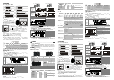
Digital I/O Terminal Wiring
08HM
DVP-08HM (8in)
X0 X X X
X X X XS/S
08HN
DVP-08HN (8out)
Y0 Y1
Y3
Y4 Y5
Y7
C0 Y2 C1
Y6
08HP
DVP- 08HP (4in/4out)
X 0
Y1 Y3
C0
Y2
Y0X 2
S /S X 1 X3
16HM
DVP- 16HM (16in)
X1 0
X 11
S /S X1 X 3
S/ S X 12 X1 3 X 14 X1 5 X1 6 X 17
X 0 X2 X4
X5
X7X6
16HP
DVP-16HP (8in/8out)
X4
X5
X 1 X3
S /S X6 X7
Y3
Y4 Y5
Y 6
X0 X 2 C 0
Y 0
Y2Y 1
Y 7
32HN
X1 5
X1 4C3
Y1 2
Y11
Y1 0
Y7
Y6
C2
Y5
Y4
Y3
C1
Y2
Y1
Y1 6
Y2 0
Y2 1 Y22 Y2 3
Y2 4 C7C6C5C4
Y2 5
Y3 0
Y3 1
Y3 5
Y3 6
Y3 4Y 3 2Y2 7Y2 6
C0
DVP-32HN(32out)
(AC Power IN)
Y3 3 Y3 7
32HP
X1 7
X16
X15
X14
X13
X12
X11
X1 0
X7
X6
X5
X4
X3
X2
X1
X0
Y0 Y1
Y2
Y3
Y4 Y5
Y6 C3C2C1C0
Y7
Y1 2
Y13
Y16
Y17
Y1 5Y1 4Y11Y1 0
S/S
DVP-32HP(16in/16out)
(AC Power IN,DC Signal IN)
48HP
X17
X16
X15
X14
X13
X12
X11
X10
X7
X6
X5
X4
X3
X2
X1
X0
Y0 Y1
Y2
Y3
Y4 Y5
Y6 C3C 2C1C0
Y7
Y12
Y13
Y16
Y17
Y15Y1 4Y11Y10
S/S
X27
X26
X25
X24
X23
X22
X21
X20
C4 Y21
Y22
Y27
Y23
Y26Y2 4Y2 0
Y25
DVP-48HP(24in/24 out)
(AC Power IN,DC Signal IN)
Mounting Arrangements and Wiring Notes
DIN Rail Installation:
The DVP-PLC can be secured to a cabinet by using the
DIN
rail that is 35mm high with a depth of 7.5mm. When
mounting the PLC on the DIN rail, be sure to use the end
bracket to stop any side-to-side motion of the PLC, thus to
reduce the chance of the wires being pulled loose. On the
bottom of the PLC is a small retaining clip. To secure the
PLC to the DIN rail, place it onto the rail and gently push up
on the clip. To remove it, pull down on the retaining clip and
gently pull the PLC away from the DIN rail. Please see the
figure on the right:
Direct Mounting: Use the specified dimensions and install with M4 screws.
For heat dissipation. Make
sure to provide a minimum
clearance of 50mm between
the unit and all sides of the
cabinet. (shown as below)
DV P MP U
> 5 0 mm
> 50mm
> 5 0mm
> 5 0mm
Wiring:
Belo w 6.2
To sui t M3.5 scr ew te rminal
Belo w 6.2
1. Please use O-type or Y-type terminals for I/O wiring terminals. The
specification for the terminals is as shown on the left.
PLC terminal screws
should be tightened to between 5 ~ 8 kg-cm (4.3 ~ 6.9 in-lbs). Use copper
conductor only, 60°C/75°C.
2. DO NOT wire to the No Function terminals . I/O signal wires or power
supply should not run through the same multi-wire cable or conduit.
3. When tightening the screws and performing wiring, please avoid that
metallic particles fall into PLC. After completing wiring, please remove the
label which is used to obstruct the metallic particles on the ventilation hole
for well heat dissipation.
4. There should be a 50mm or more distance between the PLC and other
control component. Also, keep the PLC away from high voltage line and
power equipment.
Environment:
1.
DO NOT store the PLC in an airborne dust, smoky, metallic particles, corrosive or flammable gases.
2. DO NOT store the PLC in a location where temperatures and humidity will exceed specification.
3. DO NOT mount the PLC in a location where vibration and shock will exceed specification.
I/O Point Serial Sequence
When connecting MPU with less than 32 points to extension unit, the input number of 1
st
extension unit is
started from X20 in sequence and the output number is started from Y20 in sequence. If connecting MPU with
more than 32 points to extension unit, the input number of the 1
st
extension unit is started from the last input
number of the MPU in sequence and the output number is started form the last output number of the MPU in
sequence.
MP U
EX T 1 E XT 2 EX T 3
EX T 4
PLC Model
Input
points
Output
points
Input number Output number
MPU 16EH/32EH/64EH 8/16/32 8/16/32 X0~X7/X0~X17/X0~X37 Y0~Y7/Y0~Y17/Y0~Y37
EXT1 32HP 16 16 X20~X37/X20~X37/X40~X57 Y20~Y37/Y20~Y37/Y40~Y57
EXT2 48HP 24 24 X40~X67/X40~X67/X60~X107 Y40~Y67/Y40~Y67/Y60~Y107
EXT3 08HP 4 4 X70~X73/X70~X73/X110~X113 Y70~Y73/Y70~Y73/Y110~Y113
EXT4
08HN 0 8 - Y74~Y103/Y74~Y103/Y114~Y123
In system application example, if the input/output of the 1
st
MPU are less than 16, its input/output will be defined
as 16 and thus there are no corresponding input/output for higher numbers. The input/output number of
extension number is the sequential number from the last number of the MPU.
Power Input Wiring and Specification
The power input for DVP-EH series PLC is AC input. Please pay particular attention to the following notes:
1. Connect the AC input (100 ~ 240V) to terminals L and N. Any 110V AC or 220V AC connected to the +24V
terminal or input points will permanently damage the PLC.
2. The AC power inputs for the MPU and the I/O Extension Unit should be ON or OFF at the same time.
3. Please use wires of 1.6mm or above for the grounding of the MPU.
4. If the power-cut time is less than 10ms, the PLC still operates unaffectedly. If the power-cut time is too long or
the power voltage drops, the PLC will stop operation and all outputs will be off. Once power is on again, the
PLC will resume automatically. (There are latched auxiliary relays and registers inside of the PLC, please be
aware when programming.)
AC Input
Type
L N
2.0 A
DC/DC
+5V
+24V
24G
S/S
X0 X1 X2
100~240VAC
The +24V supply output is rated at 0.5A as max. from MPU. DO NOT connect external power
supply to this termianl. Moreover, it takes 6 ~ 7mA to drive each input point, so total of 100mA
is needed for 16 input points. As a result, the output load of +24V should not exceed 400mA.
Since the PLC is in control of numerous devices, operation of either one device could affect the operation of
other devices; therefore, the breakdown of either one device would consequently be detrimental to the whole
auto control system, and danger will thus be resulted. Please use the recommended wiring below for the power
input:
Power supply for AC loads
Fuse for circuit protection (3A limit)
Power on pilot indicator
Emergency stop: a manual stop button is provided for emergency
to disconnect system power.
Circuit isolation device (System Power Disconnect): use
electromagnetic contactor and the relay to be the isolation unit of
the power circuit to prevent the possible instability of the system
when the power is supplied on and off.
DVP PLC MPU (main processing unit)
Class three grounding.
OV24 VDC
MC
MC
NL
1
1
2
3
4
5
66
8
Gua rd
Lim it
Power supply:
AC: 100 ~ 240V AC, 50/60Hz
DC: 24V DC
Input/Output Point Wiring
Input Point Wiring
There are SINK and SOURCE types for the input signal of the input point with DC input. Definition as follows:
Sink = Current flow into common terminal S/S Source = Current flows out of common terminal S/S
S/S
X0
Sinking
S/S
X0
Sourcing
Input point loop equivalent circuit Wiring loop
DC Type
(DC Signal IN)
SINK Mode
(Current flows into the
common terminal S/S)
24VDC
24G
X0
S/S
+24V
SINK
+5V
24G
S/S
X0 X1 X2+24V
Sink Type
Input point loop equivalent circuit Wiring loop
DC Type
(DC Signal IN)
SOURCE Mode
(Current flows out of
common terminal S/S)
24VDC
24G
X0
S/S
+24V
SOURCE
+5V
24G S/S X0 X1 X2+24V
Source T ype
Output Point Wiring
DO NOT wire to the No Function terminals
Fuse
Diode in reverse direction to protect the relay*1
Mutually exclusive outputs*2
Emergency stop: use an external switch
Surge absorber*3
Conductive loading
Incandescent lamp (resistive loading)
DC supply
Relay output wiring
MC2MC1
9
10
C0
C1
Y0
Y4
C2
Y2
Y3
Y5
Y1
5 2
3 7
8
1
6
7
2
5 4
MC2
MC1
AC supply
*1: There is no protection circuit for the Relay output in the PLC. If DC conductive loading is on, add a diode in reverse direction in
parallel to extend the life of the Relay. The diode in reverse direction should correspond to the following specification:
- The diode is able to withstand 5~10+ times loading voltage as maximum.
- The forward current of the diode must be greater than loading current.
*2: Use external hardware interlock and those in the PLC program to secure any emergent errors with safety protection.
*3: There is no protection circuit for the Relay in the PLC. If AC conductive loading is on, connect a surge absorber (0.1uF+ “100ohm to
120ohm”) to reduce interference and extend the life of the Relay.
DO NOT wire to the No Function terminals
Emergency stop
Fuse
Mutually exclusive output*1
DC apply
Incandescent lamp (resistive loading)
Diode in reverse direction to protect the transistor*2
Conductive loading
Transistor output wiring
MC2MC1
C0
C1
Y0
Y4
C2
Y2
Y3
Y5
Y1
5 7 8
1
6
6
4
MC2
MC1
2
3
3
9
Resistive loading
*1: Use external hardware interlock and those in the PLC program to secure any emergent errors with safety protection.
*2: Use Zener diode (39V) inside the PLC to protect the transistor. If conductive loading is on, adding a diode in reverse direction in
parallel is recommended.
(OPEN TYPE) /
( : )
/
DVP-EH EH 8 ~ 48 / 256
1
3
4
3
5
5 2
7
7
2
1
5
5
3
3
4
7
7
(mm)
DVP08HM11N 90 40 82
DVP16HM11N 90 55 82
DVP08HN11R/T 90 40 82
DVP16HP11R/T 90 55 82
3
4
2
6
6
6
7
7
33
8
9
1
10
11
(mm)
(w)
DVP32HN00R/T 90 143.5 82.2
DVP32HP00R/T 90 143.5 82.2
DVP48HP00R/T 90 174 82.2
1.
5.
9.
2. /
6.
10.
3. DIN
7.
11.
4. DIN
8.
DVP08HM11N 8 0
DVP16HM11N 16 0
DVP08HN11R 0 8
DVP08HP11R 4 4
DVP16HP11R 8 8
Relay 250V AC/30V DC 2A/1
DVP08HN11T 0 8
DVP08HP11T 4 4
DVP16HP11T
24V DC
8
DC Type
Sink/Source
8
Transistor 5 ~ 30V DC 0.3A/1
@40°C
DVP32HN00R 0 32
DVP32HP00R 16 16
DVP48HP00R 24 24
Relay 250V AC/30V DC 2A/1
DVP32HN00T 0 32
DVP32HP00T 16 16
DVP48HP00T
100 ~ 240V
AC
24
DC Type
Sink/Source
24
Transistor 5 ~ 30V DC 0.3A/1
@40 C
08HM11N
16HM11N
08HN11R/T
08HP11R/T
16HP11R/T
32HN00R/T
32HP00R/T
48HP00R/T
24V DC (20.4V DC ~ 28.8V DC) (-15% ~ 20%)
100 ~ 240V AC (-15% ~ 10%),
50/60Hz ± 5%
1W / 1.5W
1.5W 1.5W 2W 30VA 30 VA 30 VA
24V DC NA NA NA NA NA 500 mA 500 mA
24
V
DC
24V
DC
1,500V AC (Primary-secondary), 1,500V AC (Primary-PE), 500V AC (Secondary-PE)
5 MΩ / 500V DC
ESD: 8KV Air Discharge, EFT: Power Line: 2KV, Digital I/O: 1KV, Analog &
Communication I/O: 250V,
Digital I/O: 1KV, RS: 26MHz ~ 1GHz, 10V/m
L, N PLC
/
0 ~ 55°C 50 ~ 95% 2
-25 ~ 70°C 5 ~ 95%
/ IEC61131-2, IEC 68-2-6 (TEST Fc)/IEC61131-2 & IEC 68-2-27 (TEST Ea)
(g) 124/160 130/120 136/116 225/210 660/590 438/398 616/576
/
SINK SOURCE
24V DC 5mA
Off → On 16.5V DC
On → Off 8V DC
20ms
/ /LED On
-R -T
1.5A/1 5A/COM
55°C 0.1A/1 50°C 0.15A/1
45°C 0.2A/1 40°C 0.3A/1 2A/COM
250V AC,30V DC 30V DC
75VA
90 W
9W
10 ms Off → On 15us On → Off 25us