Startup Guide for RMC100 Motion Controller and RMCWin Motion Software
RMC100 Startup Guide Version 2.3 February 25, 2010 Copyright © 2010, Delta Computer Systems, Inc. www.deltamotion.com 2 deltamotion.
RMC100 Startup Contents Contents Contents ............................................................................................. 3 Overview ............................................................................................. 5 Obtaining a Manual ........................................................................... 6 Getting Started ................................................................................... 7 PC Requirements ....................................................
RMC100 Startup Overview Overview The RMC100 series brings the benefits of modular, high-performance motion control to a wide range of industrial applications. Communications options— ranging from high-speed field buses to discrete I/O and a four-line display/keypad—make these compact, DIN rail mounted controllers an excellent choice for large and small systems.
Obtaining a Manual RMC100 Startup Guide Obtaining a Manual The RMC100 motion controller manual is available in the following formats: • Complete and up-to-date information is available in the online help in the RMCWin software. • A manual containing the same information as the online help is available as a Portable Document Format (PDF) file from our web site at www.deltamotion.com. • If you need a hard-copy manual, contact Delta by telephone at 360-254-8688 or email at sales@deltamotion.com.
RMC100 Startup Getting Started Getting Started This chapter describes the minimum hardware requirements, how to install and run RMCWin, and how to set up a system with an RMC100 controller. PC Requirements Operating System Windows 98/ME/NT/2000/XP/Vista/7 Disk Space 20 Mbytes Memory 8 Mbytes Serial Port or Ethernet RS-232 or Ethernet connection required for communication with RMC100. Installation 1.
Getting Started RMC100 Startup Guide 1. Index/stored commands/Editing the Stored Command Table. This means to display the online Help, select the Index tab, type the words stored command on the edit line, and select the topic Editing the Stored Command Table. 2. Contents/Using RMCWin/Setup Options/Selecting a Serial Port to Use. This means to display the online Help, select the Contents tab, display Using RMCWin, select Setup Options, and select the topic Selecting a Serial Port to Use.
RMC100 Startup Getting Started Command area — The six registers in this area are used to send commands to the RMC100 controller. Parameter area — The sixteen registers in this area are the operational parameters. This area contains information on scaling, tuning, and configuration for fault detection. Plot Time — Specifies plot duration, or length of data log, in seconds. Toolbar — Tools in the toolbar include: Opens a new board file. Opens an existing board file. Saves the current board file.
Getting Started RMC100 Startup Guide Options dialog box appears. From the Communication tab in the Options dialog box, select the correct com port. − Contents/Using RMCWin/Connecting to an RMC/Communication Drivers/TCP/IP Direct to RMCENET Configuration • If the display indicates Closed after starting RMCWin, another program may be using the serial port. Try closing other programs that may be using the serial port.
RMC100 Startup Index/configuration/analog transducer Getting Started Analog Transducers: First, in the RMCWin Tools menu, select Module Configuration. Select the tab for the axis you are configuring, and click on Slot Option. Select the option corresponding to the type of application you have. Next, double click on the CONFIG parameter in the Parameter area to display the Analog Axis Configuration Word dialog box. Select the voltage or current range for your transducer.
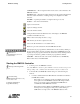
Getting Started RMC100 Startup Guide In the Command area of the RMCWin display, select the correct axis and enter the following (see Figure 3): MODE 0x0001 ACCEL 10 DECEL 10 SPEED 0 COMMAND VALUE 100 These values cause the output voltage to change to 100 mV at a rate of 10 mV/ms. Figure 3. Initial values to verify drive. button or ALT+K. Both issue a Note: Be prepared to stop the system with the Kill (K) command, which will set the drive output to 0 volts.
RMC100 Startup Getting Started 3. The actuator does not move. In this case check the output voltage, check that the actuator is enabled, verify the Simulate bit is not set in the CONFIG word, increase the voltage and repeat the process above. Note: It is essential that the COUNTS increase when a positive output voltage is specified with the “O” command. If this condition is not met, you will not be able to control the axis in closed loop. At this point the drive has moved in one direction.
Getting Started RMC100 Startup Guide After performing the startup, save your configuration settings. See the appropriate online Help topic for more information. Step-by-Step Example Appendix D contains a step-by-step, illustrated example of setting up and tuning a hydraulic cylinder. Read this to see the practical details of setup and to learn how to use the plots to tune the axis.
RMC100 Startup Features of the RMC100 Features of the RMC100 The RMC100 contains a host of useful features that will enable you to precisely and efficiently control any complex motion application. These features include powerful control options, flexible programming capabilities, effective diagnostic tools, a diverse set of feedback options, and support for many popular communication types.
Features of the RMC100 RMC100 Startup Guide S Curves Index/s curves/S curves scroll to bit 7 For applications requiring smooth motion with more gradual starts and stops and higher peak speeds, the RMC100 offers an "S-curve" option for the trapezoidal motion profile. When this option is selected, the RMC100 calculates an s-shaped target as shown below. Splines Index/Splines/Spline Overview Some applications require that the motion controller move between a number of given positions.
RMC100 Startup Features of the RMC100 Pressure or Differential Force Index/pressure control/Using Analog Channels as Pressure Inputs The RMC100 excels in pressure control applications. Control can be performed with either single-ended or double-ended pressure feedback. With double-ended pressure feedback on a hydraulic systems, the differential force on the piston can be calculated, allowing force to be controlled.
Features of the RMC100 RMC100 Startup Guide Analog Reference Index/analog transducer/overview The RMC100 analog modules can be used as reference inputs. This is very useful for applications requiring an external target generator or joystick. This externally generated voltage or current signal can then be used to generate a position or velocity target for another axis.
RMC100 Startup Features of the RMC100 • Compare functions • Math capabilities • Trigger an event sequence from a digital input • Conditional branching Master Control (PLC or PC) The RMC100 may be controlled from a PLC, a PC or other programmable controller. The RMC100 provides a full range of communication options between the RMC and the programmable controller.
Features of the RMC100 RMC100 Startup Guide Command Log Index/command log/Command Log When debugging problems with a system that is using the RMC, it is often difficult to determine whether the problem is caused by an action of the RMC or the Programmable Controller (P/C). To help with this problem, the Command Log is available. The Command Log holds the last 256 commands received through the communication module; commands sent by RMCWin or the event step table are not displayed.
RMC100 Startup Features of the RMC100 Stored Commands Index/ stored commands/ using Stored Commands are useful when setting up and tuning an axis. Setup and tuning require repetitively moving the axis. Stored Commands allow the user to enter the desired moves, and issue them with a simple key combination (e.g. CTRL-2) or by the click of a button in RMCWin. This speeds up an otherwise monotonous and time-consuming task. 21 deltamotion.
RMC100 Startup RMC100 Modules RMC100 Modules This section gives an overview of the communications and feedback capabilities of the modules available for the RMC100. Configuring an RMC100 The RMC100 series motion controllers have a modular design for configuration flexibility to meet the needs of a wide variety of applications. Due to this modular design, Delta is typically able to ship any of the more than 500 available configurations in 2 weeks or less.
RMC100 Modules RMC100 Startup Guide Communications Choices The versatile RMC100 Motion Controllers can be configured with one of five different communication modules supporting more than 25 protocols. The busbased communication modules are not just for motion data acquisition—they support full motion control via the host system. (RMC100 motion controllers also have an RS232 serial port for use with Delta’s RMCWin setup, tuning and diagnostics package.
RMC100 Startup RMC100 Modules Profibus (-PROFI) Index/Profibus/Overview The RMC100 offers a communication module for the PROFIBUS-DP open industrial Fieldbus. This Fieldbus is vendor independent and therefore a large range of Programmable Controllers (P/C) or other PROFIBUS masters can control the RMC100. • Operating baud-rates: 9.
RMC100 Modules RMC100 Startup Guide • Command Mode − • Allows any command to be sent to the motion controller and allows a wide range of status information to be sent back. This mode is more complicated than the other modes and requires a PLC for the communications, is much more capable than the other Communication Digital I/O modes. Parallel Event Mode − Can give commands to up to four axes at a time.
RMC100 Startup Modicon TSX Quantum (*2) RMC100 Modules Modicon# 140 NOE 211 00 Modicon# 140 GRP 811 00 Many options available from Schneider Electric RS-422/485 – Call Delta for info Omron C200 Omron CJ1, CJ1M and CS1 Omron# CS1W Omron CV Omron# CV500-ETN01 PC (ISA) PC (PCI) PC (3U CompactPCI) Modicon Modbus/RTU PC-based SCADA or control software that supports any of the controllers in this chart that can communicate over Ethernet SST# 5136-PFB-ISA or 5136–PBMS-ISA Lan# SMS-CIF30-PB or SMS-CI
RMC100 Modules RMC100 Startup Guide Automation Direct (www.automationdirect.com) CTI: Control Technology, Inc. (www.controltechnology.com) Delta: Delta Computer Systems, Inc. (www.deltamotion.com) GE Fanuc (www.geindustrial.com, www.gefanuc.com) Hilscher (www.hilscher.com) available through Lantronix Horner Electric APG (www.heapg.com) Lan: Lantronix (formerly Synergetic Micro Systems, Inc.) (www.synergetic.com) Mitsubishi (www.mitsubishielectric.com) Modicon or Schnieder Electric: (www.modicon.
RMC100 Startup RMC100 Modules Drive and Transducer Interface Choices Nine different I/O modules are available for the RMC100 Motion Controllers. Each motion I/O module handles two axes, and RMC100 controllers can be configured with one, two, three, or four I/O modules. I/O modules can be “mixed and matched” for control of as many as eight axes with one motion controller.
RMC100 Modules RMC100 Startup Guide drive for servo valves. The full-scale output of the VC2100 is adjustable from ±10 to ±200mA in 10mA steps. A short description of each communication module follows. The RMC part number designation of each module is in parentheses. MDT Input with Analog Output (-Mn) Index/MDT/Overview Magnetostrictive displacement transducers are designed for use in rugged industrial environments.
RMC100 Startup RMC100 Modules • Additional Inputs: − Extend (CW) Travel Limit Input − Retract (CCW) Travel Limit Input − Home Input with High-speed 50µs Position Latch − Status LED • Digital Noise Filters on All Inputs • All Discrete Inputs are Isolated • Use with Servo Drives in Velocity or Torque/Force Modes Analog Input (-An) Index/analog/Overview The RMC100 offers a 12-bit Analog Input module with no output and with optional pressure control capabilities.
RMC100 Modules RMC100 Startup Guide • Step Output • Direction Output • Drive Enable Output • Drive Fault Input Stepper Output with SSI Input (-SSTn) The RMC100 offers an SSI interface module with stepper output. It combines the features of the SSI module with the Stepper output. Additional Digital Inputs and Outputs (-Dn) Index/ digital i/o /sensor The RMC100 offers a Digital I/O module consisting of eighteen digital inputs and eight digital outputs. The outputs can be set using commands.
RMC100 Startup RMC100 Modules Transducer Compatibility with Common Manufacturers Transducer Manufacturer Balluff 800-543-8390 www.balluff.com -MDT Start-Stop and PWM supported (either edge)— specify external interrogation* RMC100 Family Interface Option -Q, -QST -SSI Quadrature MDTs: Specify a BTL5-S1xx-Mxxx-xSU040-xxx SSI Quadrature synchronous encoders transducer for motion control** Baumer Electric Ltd. 800-937-9336 www.baumerelectric.
RMC100 Startup Appendix A: Wiring Appendix A: Wiring This section describes how to wire the following RMC modules to feedback transducers and drives: • Analog • MDT • SSI • Quadrature • Quadrature (with stepper output) General Wiring Information. For CE compliance and to minimize electrical interference: Index/wiring/general • Use twisted pairs for all wiring where possible. • Use shielded cables for all wiring. • Keep RMC wiring separate from AC mains or conductors carrying high currents.
Appendix A: Wiring RMC100 Startup Guide Wiring the Analog Feedback Module Voltage Feedback Transducers Index/wiring/analog Voltage feedback transducers can be connected directly to the +In and -In connections for the desired channel. The Res connection is unused for voltage transducers.
RMC100 Startup Appendix A: Wiring Wiring the MDT Feedback Module Index/wiring/MDT RMC MDT Six-Pin Plug-in Terminal Block Pin-out Pin Function 1 2 3 4 5 6 MDT Axis + Interrogation MDT Axis - Interrogation MDT Axis Common MDT Axis + Return MDT Axis - Return Case The RMC can interface to Magnetorestrictive Displacement Transducers with either single-ended (TTL) or Differential Line Driver (RS422) interrogation signals.
Appendix A: Wiring RMC100 Startup Guide Temposonics I transducer users • Connect the transducer '+ interrogation in' wire to the ‘MDT Cmn’ pin and the transducer '- interrogation in' wire to the '-Int' pin. • CONNECT NOTHING TO THE '+Int' PIN OF THE RMC. • Connect the transducer return plus wire to the '+Ret’ pin on the RMC and the transducer return common wire to ‘MDT Cmn’ on the RMC. • CONNECT NOTHING TO THE '-Ret' PIN OF THE RMC.
RMC100 Startup Appendix A: Wiring Wiring the SSI Feedback Module Index/wiring/SSI RMC SSI Input Six-Pin Plug-in Terminal Block Pin-out Pin Function 1 2 3 4 5 6 SSI Axis + Clock SSI Axis - Clock SSI Axis Common SSI Axis + Data SSI Axis - Data Case The SSI module uses differential line driver (RS422) clock and data signals. • Connect both the +Clock and -Clock between the RMC and transducer for the clock signal, and both the +Data and -Data between the RMC and transducer for the data signal.
Appendix A: Wiring RMC100 Startup Guide 11 N/C 12 Drive* 13 Drive Cmn* Drv: blue/white Drv: white/blue 23 N/C 24 Enable*25 Enable*+ Drv: white/orange Drv: orange/white Notes: • "*" indicates outputs, all others are inputs • Color codes are for cable part number RMC-CB-QUAD-01. This cable has three wire groups: encoder, limits, and drive. The wire color column lists the wire group and the individual wire color within that group. • The encoder common should be connected to both wires listed.
RMC100 Startup Appendix A: Wiring Normally Closed recommended for Limits Drive Output Wiring Fault Input Wiring From TTL output: From Open Collector Output: Enable Output Wiring To TTL input (high = enable): 41 deltamotion.
Appendix A: Wiring RMC100 Startup Guide To active low Enable input: Wiring the Stepper Module Index/wiring/stepper Use shielded twisted pairs for all connections to inputs and outputs. Route the quadrature encoder wiring separate from other wiring. You must provide the power supplies needed by your quadrature encoders and drives, although the RMC can provide +5 VDC for the optoisolators on the drive module as shown in the Stepper Output Wiring section below.
RMC100 Startup Appendix A: Wiring Stepper Output Wiring NOTE: Do not use Vcc Out to power your encoder because: • This output’s voltage is not regulated. • 50 mA is not adequate current to power the encoder. Each of the encoder outputs (A, B, and Z) requires 20 to 25 mA in addition to the current used by the encoder’s internal circuit. • Using this output to power the encoder would violate the isolation that exists between the inputs and outputs.
Appendix A: Wiring RMC100 Startup Guide Drive with common cathode inputs: Input Wiring The wiring for all inputs is identical to the wiring for the quadrature interface module with analog outputs. See the Quadrature wiring section for diagrams on these inputs. 44 deltamotion.
RMC100 Startup Appendix B: Tuning Appendix B: Tuning After setting up your system, it must be tuned in order to control it. The better tuned a system is, the better it follows the desired trajectory and holds position. Tuning procedures differ depending on the type of system.
Appendix B: Tuning RMC100 Startup Guide Only" will make the RMC ignore the errors so you can tune the axis. This may not be possible on some systems because of safety concerns. Remember to set these bits to either "Soft Stop" or "Hard Stop" when you have gained sufficient control of the axis. • When changing the parameters, remember that they are not updated in the RMC until the Set Parameters (P) command is issued. They are not stored into the RMC FLASH memory until the Update FLASH command is issued.
RMC100 Startup Appendix B: Tuning movement. The Acceleration Feed Forward terms can help compensate for this delay. Look for following errors during acceleration and deceleration. Increase the Extend and Retract Acceleration Feed Forward terms until the errors disappear. For large masses the Acceleration Feed Forward may be in the tens of thousands. 7. Readjust the Proportional Gain Proportional Gain affects the responsiveness of the system. Low gains make the system sluggish and unresponsive.
Appendix B: Tuning RMC100 Startup Guide • If a following error occurs during acceleration and deceleration and adjusting the Gains and Acceleration Feed Forward does not help, the Acceleration and Deceleration ramps are too steep for the response of the system. • If the actual position lags or leads the target position during the entire constant velocity section of the move, adjust the Feed Forwards. • Should the system seem a little sloppy, try adjusting the Proportional Gain.
RMC100 Startup Appendix B: Tuning c) Repeat b until sufficient damping is obtained. There are several methods to do this, depending on the system: − For small motors, rotate the motor manually to get a feel for the resistance to movement (damping). Repeat step b until the damping is significant. If the motor chatters or oscillates, decrease the gain.
Appendix B: Tuning RMC100 Startup Guide the axis. Note that not all systems allow the differential gain to be set high enough for the drive to be "fuzzy". A disadvantage of Differential Gain is that it amplifies position measurement noise. If there is too much noise or the gain is too high, this can cause the system to chatter or oscillate. 10. Increase System Speed Gradually increase the Speed and Acceleration values while making long moves. Look for following errors, overshoot, or oscillations.
RMC100 Startup Appendix B: Tuning • Select the transducer type you have. See MDT configuration for more details on the Configuration word. iii. Set scale and offset • On the Tools menu, click MDT Scale/Offset Calibration. • In the Desired Position Units field, enter the desired measurement units. Many position/pressure applications use 1000 units per inch. • In the Transducer field, enter the transducer data. This information is available from the transducer specifications.
Appendix B: Tuning RMC100 Startup Guide • Double-click the Config Word (in the parameter area of the main screen) for the pressure axis. • In the Input type field, select the type of feedback of your pressure transducer. iii. Set scale and offset • On the Tools menu, click Scale/Offset Calibration. • If the axis is pressure control: Enter the desired Actual Pressure for two different pressure counts (the counts are the feedback from the transducer).
RMC100 Startup Appendix B: Tuning commands numerous times. Doing this from a PLC or by typing commands in RMCWin is very awkward. To simplify the process, Event Steps in RMCWin should be used for setting up and tuning position/pressure control. To perform position/pressure control, the following steps must be set up in the Event Step Table: 1. Issue a P command so the axis will hold position. 2. Issue a Set Null Drive to Integral Drive (n) command.
Appendix B: Tuning RMC100 Startup Guide Step 0: This step is normally linked to after finishing a sequence. If the event control is at step 0, it usually means the event control has stopped. This step does nothing. Step 1: Issues a P command so the axis will hold position. Waits for 1/2 sec so the drive output will stabilize for the next step. Step 2: Issues a Set Null Drive to Integral Drive. This updates the null drive (drive needed to hold position), which is critical for pressure control.
RMC100 Startup Appendix B: Tuning and Set Parameters (P) commands will not be sent to the pressure axis because they are also valid on the position axis. • When editing the event table you will have to keep in mind that for pressure commands, you should enter values for Pressure Set A in the Acceleration field, values for Pressure Set B in the Deceleration field, and values for Ramp Time in the Speed field. Once you have set up your Event Steps table, continue to Tuning a Position/Pressure System.
Appendix B: Tuning RMC100 Startup Guide 4. Add Filter if Necessary If the pressure feedback signal is excessively noisy, it may cause instability and will likely have been noticed already in the previous step. Adding a filter may help. This is done using the Filter TC parameter. See Filter TC for detailed information. 5. Adjust the Integral Gain The Integral Gain helps get to the command pressure quickly. 6. 7. 8. • Use the same Event Step sequence as previously to ramp between two pressures.
RMC100 Startup Appendix B: Tuning 9. • Selecting Calculate Ramp Time in the Mode word allows the RMC to automatically calculates the Ramp Time. This is useful if it is difficult to determine a Ramp Time. • The following three steps also address parameters affecting the transition. Adjust the Feed Forwards The Extend and Retract Feed Forwards provide extra drive when extending or retracting. • Adjust the Feed Forwards to help the actual pressure track the target pressure when it is changing.
Appendix B: Tuning RMC100 Startup Guide • Adding or changing the Filter TC value may help if noisy feedback is suspected. • Note that tuning pressure is often very difficult because of the large change in pressure for a small change in position. 58 deltamotion.
RMC100 Startup Appendix C: An Example Appendix C: An Example Example Setup & Tuning of a Hydraulic System Index/position-pressure transition/position-pressure example This illustrated step-by-step example covers setting up and tuning a hydraulic position axis. This example uses a hydraulic system set up for position/pressure control, but will only treat the position portion. For a position/pressure example, see the online help.
Appendix C: An Example RMC100 Startup Guide 4. • Axes 0 and 1 are the two MDT axes. • The other axes are for pressure and can be ignored for this example. Configuring the MDT position axis. To scale the MDT position axis, do the following: • On the Tools menu, click Module Configuration. • In the Slots field, click on MDT, which opens the following window: • It is already set to 21 µs, which is correct. If the MDT transducer is a clevis-mount type, choose 5 µs. • Click Update RMC.
RMC100 Startup Appendix C: An Example 5. • In the Transducer Type field, select Start/Stop (Rising Edge). • Leave all the other settings as they are. • Click OK. • Issue a Set Parameters (P) command to Axis 0. Scaling the MDT position axis. To scale the MDT position axis, do the following: • Click on any Axis 0 field. • On the Tools menu, click MDT Scale/Offset Calibration. The following window opens: 61 deltamotion.
Appendix C: An Example RMC100 Startup Guide • The position feedback is to be measured in thousandths of inches, so 1000 position units per inch is entered in the Desired Position Units field. • The transducer gradient information in the Transducer field is found on the transducer. • To set the offset, the following steps are performed − Retract the cylinder all the way. This can be done by issuing anOpen Loop (O) command with a small amount of drive.
RMC100 Startup Appendix C: An Example • Check the deadband. This system has a very small deadband, approx 5 millivolts, so we will not worry about it. • Set the gains and feed forwards to zero and issue a Set Parameters (P) command. • Double-click the Axis 0 Auto Stop word (in the Parameters field). − Set the Overdrive, Integrator Windup and Overdrive bits to Status only. • Set the proportional gain to a small value, such as 5. Issue a Set Parameters (P) command.
Appendix C: An Example RMC100 Startup Guide − The detail window in the plot may be opened by clicking Show Detail Window on the Data menu. The detail window provides much useful information. − In this plot, the colored lines represent: Red ........................................... Actual Position Dark Blue-Green ...................... Target Position (Desired Position) Blue .......................................... Actual Speed Pink .......................................... Target Speed Green......
RMC100 Startup Appendix C: An Example − The position lags during the constant speed portion of the move, which the next step will address. • Make a fairly long move without any oscillations. Issue a Feed Forward Adjust (F) command. The Retract Feed Forward value is automatically updated to 84 in this case. • Make a move in the opposite direction. Issue a Feed Forward Adjust (F) command. The Extend Feed Forward value is automatically updated to 84 in this case. • Make a move.
Appendix C: An Example RMC100 Startup Guide − If the system starts oscillating or chattering, decrease the Differential Gain. − The Sum Error2 decreased to 177,000. • Increase the Acceleration Feed Forwards to get rid of the following errors during acceleration and deceleration. • After increasing the Acceleration Feed Forwards to 200, the plot looks like this: − The Sum Error2 decreased to 13,000! • − The overshoot disappeared.
RMC100 Startup Appendix C: An Example • Now that the system is tuned, it is important to enable any Auto Stops that were set to Status Only. Double-click the Axis 0 Auto Stop field. The following window appears: • On most systems, it is preferable to have any axis errors cause a Soft or Hard Stop for safety. Additionally, Soft Stops are often desirable because they slowly stop the axis.
Appendix C: An Example RMC100 Startup Guide • The RMCWin window now looks like this: • The system is now ready to be used for more complicated commands, such as speed control, gearing, splines, synchronized moves, etc. 68 deltamotion.