(Model SA150) PART NO. 905593 - 05-31-02 Copyright © 2002 Delta Machinery To learn more about DELTA MACHINERY visit our website at: www.deltamachinery.com. For Parts, Service, Warranty or other Assistance, please call ESPAÑOL: PÁGINA 13 1-800-223-7278 (In Canada call 1-800-463-3582).
GENERAL SAFETY RULES Woodworking can be dangerous if safe and proper operating procedures are not followed. As with all machinery, there are certain hazards involved with the operation of the product. Using the machine with respect and caution will considerably lessen the possibility of personal injury. However, if normal safety precautions are overlooked or ignored, personal injury to the operator may result.
ADDITIONAL SAFETY RULES FOR BELT / DISC SANDERS WARNING: FAILURE TO FOLLOW THESE RULES MAY RESULT IN SERIOUS PERSONAL INJURY. 1. DO NOT OPERATE THIS MACHINE until it is assembled and installed according to the instructions. 17. AVOID awkward hand positions where a sudden slip could cause a hand to move into the sanding belt or disc. 2. OBTAIN ADVICE FROM YOUR SUPERVISOR, instructor, or another qualified person if you are not familiar with the operation of this machine. 18.
POWER CONNECTIONS A separate electrical circuit should be used for your machines. This circuit should not be less than #12 wire and should be protected with a 20 Amp time lag fuse. If an extension cord is used, use only 3-wire extension cords which have 3prong grounding type plugs and matching receptacle which will accept the machine’s plug.
EXTENSION CORDS MINIMUM GAUGE EXTENSION CORD RECOMMENDED SIZES FOR USE WITH STATIONARY ELECTRIC MACHINES Use proper extension cords. Make sure your extension cord is in good condition and is a 3-wire extension cord which has a 3-prong grounding type plug and matching receptacle which will accept the machine’s plug. When using an extension cord, be sure to use one heavy enough to carry the current of the machine.
ASSEMBLY WARNING: FOR YOUR OWN SAFETY, DO NOT CONNECT THE MACHINE TO THE POWER SOURCE UNTIL THE MACHINE IS COMPLETELY ASSEMBLED AND YOU READ AND UNDERSTAND THE ENTIRE INSTRUCTION MANUAL. BELT SANDER TABLE 1. DISCONNECT MACHINE FROM POWER SOURCE. G 2. Locate the M8x1.25x30mm hex head screw (A) Fig. 2, M8.4 flat washer (B), and table locking handle assembly (C), (D), (E) and (F). NOTE: The table locking assembly (C, D, E, and F) is shipped assembled.
A A B B Fig. 8 Fig. 7 A ABRASIVE TO SANDING DISC 1. DISCONNECT MACHINE FROM POWER SOURCE. 2. Remove one-half of the abrasive backing (A) Fig. 7, to expose the adhesive. 3. Attach the lower section of the abrasive to the sanding disc (B), making sure that the abrasive edges fit the sanding disc edges exactly. B 4. Remove the other half of the abrasive backing. Fig. 9 5. Attach the upper edge of the abrasive backing to the sanding disc.
OPERATING CONTROLS AND ADJUSTMENTS STARTING AND STOPPING SANDER The switch (A) Fig. 15 is located on the top of the switch box. To start the sander, move the switch forward to the “ON” position. To stop the sander, move the switch back to the “OFF” position. A Fig. 15 B LOCKING SWITCH IN THE “OFF” POSITION IMPORTANT: When the tool is not in use, the switch should be locked in the OFF position using a padlock (B) Fig. 16, with a 3/16" diameter shackle to prevent unauthorized use. Fig.
E 4. The table can be tilted to the front (Fig. 19), by loosening table locking handle (C), tilting the table to the desired angle and tightening the table locking handle (C). D 5. The table can be adjusted in or out by loosening the table locking handle and moving the table in or out. Retighten lock handle when the adjustment has been made.
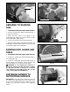
CHANGING ABRASIVE BELT A 1. DISCONNECT MACHINE FROM POWER SOURCE. 2. Remove lock knob (A) Fig. 23, and remove side cover (B). B 3. Depress tracking knob (C) Fig. 24, to release belt tension and remove belt (D) from the three wheels (E), as shown. Fig. 23 4. Install new belt and replace side cover. Check belt tracking by referring to the section “TRACKING THE BELT”. E C D Fig. 24 B CHANGING SANDING DISC 1. DISCONNECT MACHINE FROM POWER SOURCE. 2 Remove the two screws, one of which is shown (A) Fig.
A A B B Fig. 27 Fig. 28 MITER GAGE DUST CHUTES A miter gauge (A) Fig. 27, is supplied with your sander and can be used on the disc table. The miter gauge head (A) can be set up to 45 degrees right or left by loosening lock knob (B), moving miter gauge head to the desired angle and tightening lock knob (B). Two dust chutes are supplied with your belt and disc sander. Equipped with 1-1/2" I.D. openings, these can easily be connected to a dust bag. Dust chute (A) Fig.
PARTS, SERVICE OR WARRANTY ASSISTANCE All Delta Machines and accessories are manufactured to high quality standards and are serviced by a network of Porter-Cable • Delta Factory Service Centers and Delta Authorized Service Stations. To obtain additional information regarding your Delta quality product or to obtain parts, service, warranty assistance, or the location of the nearest service outlet, please call 1-800-223-7278 (In Canada call 1-800-463-3582).