SA350K Bench Oscillating Spindle Sander Ponceuse d’établi à broche oscillante Lijadora de eje oscilante de banco Instruction Manual Manuel d’utilisation Manual de instrucciones FRANÇAIS (12) ESPAÑOL (22) www.deltamachinery.com A20932_04-23-07_Rev.
TABLE OF CONTENTS IMPORTANT SAFETY INSTRUCTIONS ....................2 SAFETY GUIDELINES - DEFINITIONS .....................2 GENERAL SAFETY RULES .......................................3 ADDITIONAL SPECIFIC SAFETY RULES ................4 FUNCTIONAL DESCRIPTION ...................................6 CARTON CONTENTS ...............................................6 ASSEMBLY .................................................................7 OPERATION ...............................................................
1. 2. 3. FOR YOUR OWN SAFETY, READ THE INSTRUCTION MANUAL BEFORE OPERATING THE MACHINE. Learning the machine’s application, limitations, and specific hazards will greatly minimize the possibility of accidents and injury. WEAR EYE AND HEARING PROTECTION. ALWAYS USE SAFETY GLASSES. Everyday eyeglasses are NOT safety glasses. USE CERTIFIED SAFETY EQUIPMENT. Eye protection equipment should comply with ANSI Z87.1 standards. Hearing equipment should comply with ANSI S3.19 standards. WEAR PROPER APPAREL.
ADDITIONAL SPECIFIC SAFETY RULES Failure to follow these rules may result in serious personal injury. 1. 2. 3. 4. 5. 6. 7. 8. 9. 10. 11. 12. 13. DO NOT OPERATE THIS MACHINE until it is completely assembled and installed according to the instructions. A machine incorrectly assembled can cause serious injury. OBTAIN ADVICE from your supervisor, instructor, or another qualified person if you are not thoroughly familiar with the operation of this machine.
POWER CONNECTIONS A separate electrical circuit should be used for your machines. This circuit should not be less than #12 wire and should be protected with a 20 Amp time lag fuse. If an extension cord is used, use only 3-wire extension cords which have 3-prong grounding type plugs and matching receptacle which will accept the machine’s plug.
EXTENSION CORDS MINIMUM GAUGE EXTENSION CORD RECOMMENDED SIZES FOR USE WITH STATIONARY ELECTRIC MACHINES Use proper extension cords. Make sure your extension cord is in good condition and is a 3-wire extension cord which has a 3-prong grounding type plug and matching receptacle which will accept the machine’s plug. When using an extension cord, be sure to use one heavy enough to carry the current of the machine.
ASSEMBLY For your own safety, do not connect the machine to the power source until the machine is completely assembled and you read and understand the entire instruction manual. ASSEMBLY TOOLS REQUIRED 3/16" Hex Wrench (Supplied) 1/2" Socket Wrench (Supplied) 7/16' open-end wrench ASSEMBLY TIME ESTIMATE Assembly for this machine takes less than 1/2 hour. 1. Carefully turn the machine upside down. Place it on a clean, firm, supporting surface. 2.
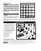
ATTACHING THE SANDING DRUM, ABRASIVE SLEEVE AND TABLE INSERT C E D D F A E G C FIG. 6 FIG. 5 C F G G D H FIG. 7 FIG.8 1. Place the 2-3/8" diameter washer (A) on the spindle. 2. Select the correct abrasive sleeve for your workpiece. 3. Slide that abrasive sleeve (C) Figs. 5 and 6 over the matching sanding drum (D) Figs. 5 and 6. Position this assembly on the spindle adapter. Place the matching washer (A) Fig.
OPERATION OPERATIONAL CONTROLS AND ADJUSTMENTS STARTING AND STOPPING THE SANDER The on/off switch (A) Fig. 12 is located on the sander base. To turn the sander “ON”, move the switch up to the “ON” position. To turn the sander “OFF”, move the switch down to the “OFF” position. A FIG. 11 LOCKING THE SWITCH IN THE “OFF” POSITION IMPORTANT: When the machine is not in use, the switch should be locked in the "OFF" position to prevent unauthorized use.
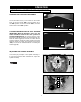
MACHINE USE Sanding inside curves is illustrated in Fig. 16. IMPORTANT: Always sand against the rotation of the sanding drum. The oscillating action of the sanding drum minimizes score marks and prevents clogging of the sanding drum, providing faster, smoother sanding and increasing the life of the sanding sleeve. FIG. 16 TROUBLESHOOTING For assistance with your machine, visit our website at www.deltamachinery.
FREE WARNING LABEL REPLACEMENT If your warning labels become illegible or are missing, call 1-800-223-7278 for a free replacement. TO REDUCE THE RISK OF INJURY KEEP HANDS AWAY FROM MOVING PARTS PARA REDUCIR EL RIESGO DE LESIONES MANTENGA LAS MANOS LEJOS DE LAS PIEZAS EN MOVIMIENTO AFIN DE RÉDUIRE LE RISQUE DE BLESSURES ÉLOIGNER LES MAINS DES PIÈCES MOBILES A21636 SERVICE AND REPAIRS All quality tools will eventually require servicing and/or replacement of parts.
LES INSTRUCTIONS IMPORTANTES DE SURETE Lire et comprendre toutes instructions d'avertissements et opération avant MESURES DE SÉCURITÉ - DÉFINITIONS Ce guide contient des renseignements importants que vous deviez bien saisir. Cette information porte sur VOTRE SÉCURITÉ et sur LA PRÉVENTION DE PROBLÈMES D’ÉQUIPEMENT. Afin de vous aider à identifier cette information, nous avons utilisé les symboles ci-dessous. Veuillez lire attentivement ce guide en portant une attention particulière à ces sections.
RÈGLES DE SÉCURITÉ GÉNÉRALES L’inobservation de ces règles peut conduire à des blessures graves. 14. UTILISER LE CORDON PROLONGATEUR APPROPRIÉ. S’assurer que le cordon prolongateur est en bon état. Lorsqu’un cordon prolongateur est utilisé, s’assurer que celui-ci est d’un calibre suffisant pour l’alimentation nécessaire à la machine. Un cordon d’un calibre insuffisant entraînera une perte de tension d’où une perte de puissance et surchauffe.
RÈGLES SPÉCIFIQUES ADDITIONNELLES DE SÛRETÉ L’inobservation de ces règles peut conduire à des blessures graves. 1. 2. 3. 4. 5. 6. 7. 8. 9. 10. 11. 12. 13. NE PAS FAIRE FONCTIONNER CET APPAREIL avant qu’il ne soit entièrement assemblé et installé conformément à ces directives. Un appareil mal assemblé peut provoquer des blessures graves. DEMANDER CONSEIL à un superviseur, à un instructeur ou à toute autre personne qualifiée si l’utilisation de cet appareil n’est pas parfaitement maîtrisée.
RACCORDEMENTS ÉLECTRIQUES Un circuit électrique séparé doit être utilisé pour les machines. Les fils de ce circuit doivent être au moins de calibre 12. Ce circuitdoit être protégé par un fusible temporisé de 20 A. Si on utilise un cordon prolongateur, ce cordon doit être à trois fils, avoir unefiche à trois broches et une prise de courant à trois cavités, mise à la terre qui correspond à la fiche de la machine.
CORDON DE RALLONGE MESUR MINIMUM DE CORDE D’EXTENSION TAILLES RECOMMANDÉES POUR L'CUSAGE AVEC STATIONNAIRES ÉLECTRIQUES LES OUTILS Employez les cordes appropriées de prolongation. S'assurent votre corde de prolongation est en bon état. En utilisant une corde de prolongation, soyez sûr d'employer un assez lourd pour porter le courant de la machine. Une corde trop petite causera une baisse dans la tension secteur, ayant pour résultat la perte de puissance et de surchauffe. Fig.
ASSEMBLAGE Pour votre propre sûreté, ne reliez pas la machine à la source d'énergie jusqu'à ce que la machine soit complètement assemblée et vous lisez et comprenez le manuel d'instruction entier. OUTILS NÉCESSAIRES POUR L’ASSEMBLEE Clé hexagonale de 3/16 po (fournie) Clé à douille de 1/2 po (fournie) Clé à fourche de 7/16 po L'ESTIMATION DE TEMPS D'ASSEMBLEE L’Assemblée pour cette machine prend moins de 30 minutes. 1. Mettre l’appareil à l’envers avec soin.
ASSEMBLER LE CYLINDRE DE CONTACT, LE MANCHON ABRASIF ET LA PLAQUE AMOVIBLE C E D D F A E G C FIG. 6 FIG. 5 C F G G D H FIG. 7 FIG.8 Placer la rondelle 2-3/8"de diamètre (A) sur de broche. Sélectionner le manchon abrasif approprié pour la pièce. Glisser ce manchon abrasif (C), fig. 5 et 6, sur le cylindre de contact correspondant (D), fig. 5 et 6. Positionner cet assemblage sur l’adaptateur de broche. Enfiler la rondelle correspondante (A), fig.
FONCTIONNEMENT L'OPERATION CONTROLE DE LE ET LES AJUSTEMENTS DÉMARRAGE ET ARRÊT DE LA MACHINE L'interrupteur (on-off) (A) fig. 12 est localisée sur la base. Pour allumer la ponceuse, déplacer le commutateur jusqu'à le « SUR » la position. Pour éteindre la ponceuse, descendre le commutateur au « DE » la position. A FIG.
MACHINE USE Le ponçage des courbes internes est illustré à la fig. 16. IMPORTANT : toujours poncer à l’opposé de la rotation du cylindre de contact. Le mouvement oscillant du cylindre de contact minimise l’apparition de raies et empêche le bourrage du cylindre de contact pour un ponçage plus rapide et régulier et pour une durée d’utilisation accrue du manchon abrasif. FIG. 16 DEPANNAGE Pour l'assistance avec votre outil, visiter notre site web à www.deltamachinery.
REMPLACEMENT GRATUIT DE L'ÉTIQUETTE Si vos étiquettes d'avertissement deviennent illisibles ou sont manquantes, composez le 1-800-223-7278 pour obtenir une étiquette de remplacement gratuite. TO REDUCE THE RISK OF INJURY KEEP HANDS AWAY FROM MOVING PARTS PARA REDUCIR EL RIESGO DE LESIONES MANTENGA LAS MANOS LEJOS DE LAS PIEZAS EN MOVIMIENTO AFIN DE RÉDUIRE LE RISQUE DE BLESSURES ÉLOIGNER LES MAINS DES PIÈCES MOBILES A21636 TO REDUCE THE RISK OF INJURY READ INSTRUCTION MANUAL BEFORE OPERATING SANDER.
INSTRUCCIONES DE SEGURIDAD IMPORTANTES Lea y entienda todas advertencias y las instrucciones operadoras antes de utilizar cualquier instrumento o el equipo. Cuando se usa instrumentos o equipo, las precauciones básicas de la seguridad siempre se deben seguir para reducir el riesgo de la herida personal. La operación impropia, la conservación o la modificación de instrumentos o equipo podrían tener como resultado el daño grave de la herida y la propiedad.
NORMAS GENERALES DE SEGURIDAD Si no se siguen estas normas, el resultado podría ser lesiones graves. 1. 2. 3. 4. 5. 6. 7. 8. 9. 10. 11. 12. 13. 14. UTILICE EL CORDÓN DE EXTENSIÓN ADECUADO. Asegúrese de que el cordón de extensión esté en buenas condiciones. Cuando utilice un cordón de extensión, asegúrese de utilizar un cordón que sea lo suficientemente pesado como para llevar la corriente que su producto tome.
NORMAS ESPECÍFICAS ADICIONALES DE SEGURIDAD Si no se siguen estas normas, el resultado podría ser lesiones personales graves. 1. 2. 3. 4. 5. 6. 7. 8. 9. 10. 11. 12. 13. 14. NO OPERE ESTA MÁQUINA hasta que no esté armada e instalada completamente, según las instrucciones. Una máquina montada de manera incorrecta puede provocar lesiones graves. SOLICITE EL ASESORAMIENTO de su supervisor, su instructor o alguna persona calificada si no está familiarizado con el funcionamiento de esta máquina.
CONEXIONES A LA FUENTE DE ALIMENTACIÓN Debe utilizarse un circuito eléctrico independiente para las máquinas. Este circuito debe tener alambre de no menos del No. 12 y debe estar protegido con un fusible de acción retardada de 20 A. Si se utiliza un cordón de extensión, utilice únicamente cordones de extensión de tres alambres que tengan enchufes de tipo de conexión a tierra con tres terminales y un receptáculo coincidente que acepte el enchufe de la máquina.
CORDONES DE EXTENSIÓN CORDÓN DE EXTENSIÓN DE CALIBRE MÍNIMO TAMAÑOS RECOMENDADOS PARA USO CON MÁQUINAS ELÉCTRICAS ESTACIONARIAS Utilice cordones de extensión apropiados. Asegúrese de que el cordón de extensión esté en buenas condiciones y de que sea un cordón de extensión de tres alambres que tenga un enchufe de tipo de conexión a tierra con tres terminales y un receptáculo coincidente que acepte el enchufe de la máquina.
ENSAMBLAJE Para su propia seguridad, no conecte la maquina a la fuente de energia hasta que la maquina haya sido ensamblada por completo y usted haya leido y entendido completamente el manual del propietario. HERRAMIENTAS DE ENSAMBLAJE REQUERIDAS Llave hexagonal de 3/16" (suministrada) Llave para enchufes de 1/2" (suministrada) Llave abierta de 7/16" ESTIMACIÓN DEL TIEMPO DE ENSAMBLAJE La asamblea para esta máquina toma menos de 1/2 hora. 1. Invierta cuidadosamente la máquina.
INSTALACIÓN DEL TAMBOR DE LIJADO, EL MANGUITO ABRASIVO Y EL INSERTO DE MESA C E D D F A E G C FIG. 6 FIG. 5 C F G G D H FIG. 7 FIG.8 1. 2. 3. Coloque la arandela del diámetro (A) en el eje. Seleccione el manguito abrasivo adecuado para su pieza de trabajo. Deslice ese manguito abrasivo (C) Figs. 5 y 6 sobre el tambor de lijado correspondiente (D) Figs. 5 y 6. Coloque este ensamble sobre el adaptador del eje. Coloque la arandela correspondiente (A) Fig.
OPERACIÓN CONTROLES Y AJUSTES OPERACIONALES ARRANCANDO Y DETENIENDO LA MAQUINA El en/lejos cambia (A) Fig. 12 son localizados en la base. Para prender la lijadora, mueva el interruptor hasta el "EN" la posición. Para apagar la lijadora, mueve el interruptor hacia abajo al "DE" la posición. A FIG. 11 FIJANDO EL INTERRUPTOR EN LA POSICION DE APAGADO IMPORTANTE: Cuándo la herramienta no es adentro uso, el interruptor se debe bloquear en el OFF posición para prevenir uso desautorizado.
UTILIZAR LA MAQUINA El lijado de curvas internas se muestra en la Fig. 16. IMPORTANTE: Siempre lije en sentido contrario a la rotación del tambor de lijado. El movimiento oscilante del tambor de lijado minimiza las rayas y evita el atascamiento del tambor de lijado, lo cual produce un lijado más rápido y suave y prolonga la vida útil del manguito de lijado. FIG. 16 LOCALIZACION DE FALLAS Para obtener asistencia para su máquina, visite nuestro sitio Web en www.deltamachinery.
Una línea completa de accesorios está disponible de su surtidor de Porter-Cable • Delta, centros de servicio de la fábrica de PorterCable • Delta, y estaciones autorizadas delta. Visite por favor nuestro Web site www.deltamachinery.com para un catálogo o para el nombre de su surtidor más cercano.
Garantía limitada de dos años para productos nuevos Delta reparará o reemplazará, a expensas y opción propias, cualquier máquina nueva, pieza de máquina nueva o accesorio de máquina nuevo Delta que durante el uso normal haya presentado defectos de fabricación o de material, siempre que el cliente devuelva el producto con el transporte prepagado a un centro de servicio de fábrica Delta o una estación de servicio autorizado Delta, con un comprobante de compra del producto, dentro del plazo de dos años y dé a