(Model SA446) PART NO. 905578 -05-03-02 Copyright © 2002 Delta Machinery To learn more about DELTA MACHINERY visit our website at: www.deltamachinery.com. For Parts, Service, Warranty or other Assistance, please call ESPAÑOL: PÁGINA 21 1-800-223-7278 (In Canada call 1-800-463-3582).
GENERAL SAFETY RULES Woodworking can be dangerous if safe and proper operating procedures are not followed. As with all machinery, there are certain hazards involved with the operation of the product. Using the machine with respect and caution will considerably lessen the possibility of personal injury. However, if normal safety precautions are overlooked or ignored, personal injury to the operator may result.
ADDITIONAL SAFETY RULES FOR BELT / DISC SANDERS WARNING: FAILURE TO FOLLOW THESE RULES MAY RESULT IN SERIOUS PERSONAL INJURY. 17. DO NOT sand pieces of material that are too small to be safely supported. 1. DO NOT operate your machine until it is completely assembled and installed according to the instructions. 18. AVOID awkward hand positions where a sudden slip could cause a hand to move into the sanding belt or disc. 2.
POWER CONNECTIONS A separate electrical circuit should be used for your machines. This circuit should not be less than #12 wire and should be protected with a 20 Amp time lag fuse. If an extension cord is used, use only 3-wire extension cords which have 3prong grounding type plugs and matching receptacle which will accept the machine’s plug.
EXTENSION CORDS Use proper extension cords. Make sure your extension cord is in good condition and is a 3-wire extension cord which has a 3-prong grounding type plug and matching receptacle which will accept the machine’s plug. When using an extension cord, be sure to use one heavy enough to carry the current of the machine. An undersized cord will cause a drop in line voltage, resulting in loss of power and overheating. Fig. D, shows the correct gauge to use depending on the cord length.
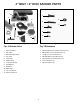
4" BELT / 6" DISC SANDER PARTS 1 1 2 6 4 2 3 7 6 3 8 5 7 4 11 9 5 10 12 Fig. 1A Fig. 1B Fig. 1A Sander Parts Fig. 1B Hardware 1. Motor and Base 1. M8x1.25x20mm Hex Socket Head Screw (3) 2. Disc Table 2. M6x1x30mm Cheese Head Screws (2) 3. Belt and Pulley Guard 3. 1/4-20x1/2" Hex Head Screw (1) 4. Disc Plate 4. M5x.08x10mm Pan Head Screw (3) 5. Dust Chute 5. M4x.7x12mm Sheet Metal Screw (3) 6. Support Rod 6. 5/16" Flat Washer (1) 7. Lower Disc Guard 7. M5.3 Flat Washer (3) 8.
ASSEMBLY INSTRUCTIONS WARNING: FOR YOUR OWN SAFETY, DO NOT CONNECT THE SANDER TO THE POWER SOURCE UNTIL THE MACHINE IS COMPLETELY ASSEMBLED AND YOU READ AND UNDERSTAND THE ENTIRE OWNERS MANUAL. D E B ADJUSTING BELT TENSION Your sander was shipped from the factory with the drive belt (A) Fig. 2, assembled to both pulleys (B) and (C). Before assembling the machine, check and adjust the belt tension as follows: A C Fig. 2 1. Loosen screw (D) Fig.
ASSEMBLING BELT AND PULLEY GUARD A Assemble the belt and pulley guard (A) Fig. 5, to the machine base using the two M6x1x30mm cheese head screws (B), as shown. B Fig. 5 ASSEMBLING SANDING DISC PLATE B 1. Back the 1/4-20x1/4" hex socket set screw (A) Fig. 6, out of the hole, just enough so that the set screw is not extending into hole (B) Fig. 6, in the sanding plate. A Fig. 6 2. Slide sanding disc plate (B) Fig.
ASSEMBLING SANDING DISC 1. A Make sure sanding disc plate (A) Fig. 9, is clean. 2. Peel backing from sanding disc and press disc (B) firmly into position all the way around the sanding plate, as shown in Fig. 9. B Fig. 9 ASSEMBLING LOWER COVER FOR SANDING DISC Assemble the lower cover (A) Fig. 10, to the belt and pulley guard, using the three M4x.7x12mm sheet metal screws (B). A B Fig. 10 ASSEMBLING DISC SANDER TABLE 1. Thread a M8x1.25x20mm hex socket head screw (A) Fig.
ASSEMBLING DUST CHUTE Align the three holes in the dust chute (A) Fig. 13 with the three holes in the left side of the sanding base. Place a M5.3 flat washer onto a M5x.08x10mm pan head screw (B) Fig. 13, and insert screw through hole in dust spout and thread into taped hole in sander base. Repeat this process for the two remaining holes. B A Fig. 13 ASSEMBLING BACKSTOP TO SANDING ARM A Assemble backstop (A) Fig. 14, to the sanding arm using the 1/4-20x1/2" hex head screw (B) and 5/16" flat washer (C).
3. An alternate method of securing the sander to a supporting surface is to fasten the sander base to a mounting board 18" x 24" minimum size. The diagram, shown in Fig. 17, illustrates the size and center to center distance of the holes to be drilled in the mounting board. NOTE: For proper stability, the holes in the mounting board must be countersunk at the bottom so screw heads are flush with bottom surface of the mounting board. Fig. 17 4.
LOCKING SWITCH IN THE “OFF” POSITION IMPORTANT: When the machine is not in use, the switch should be locked in the “OFF” position to prevent unauthorized use. This can be done by grasping the switch toggle (B) Fig. 23, and pulling it out of the switch as shown. With the switch toggle (B) removed, the switch will not operate. However, should the switch toggle be removed while the machine is running, it can be turned “OFF” once, but cannot be restarted without inserting the switch toggle (B). B Fig.
ADJUSTING BACKSTOP SQUARE WITH SANDING BELT 1. A DISCONNECT MACHINE FROM POWER SOURCE. 2. When making this adjustment make sure the belt tension lever (A) Fig. 28, is all the way to the left in the tightened position, as shown. Fig. 28 3. Place a square (B) Fig. 29, on the sanding belt with one end of the square against the backstop, and check to see if the backstop is square with the sanding belt. B 4. If an adjustment is necessary, loosen screw (C) Fig. 29, and adjust the backstop accordingly.
A ADJUSTING MITER GAGE SLOT PARALLEL WITH SANDING DISC 1. DISCONNECT MACHINE FROM POWER SOURCE. Fig. 32 2. Using a combination square (A) in the miter gage slot, check the distance from the slot to each end of the sanding disc, as shown in Figs. 32 and 33. This distance should be the same. A Fig. 33 3. If an adjustment to the table is necessary, loosen the three screws (B) Fig.
USING TABLE ASSEMBLY WITH SANDING BELT A C When the sanding arm (A) Fig. 36, is used in the vertical position, the complete table assembly (B) can be moved from the disc unit to the belt unit as follows: 1. DISCONNECT MACHINE FROM POWER SOURCE. 2. Remove the backstop (C) Fig. 36. D G B F 3. Thread the M8x1.25x20mm hex socket head screw (D) Fig. 36, into base casting as shown. NOTE: Only thread screw (D) partway into base casting. E Fig. 36 4. Loosen screw (E) Fig.
REPLACING SANDING BELT 1. DISCONNECT MACHINE FROM POWER SOURCE. 2. Loosen screw (A) Fig. 40, and remove backstop (B). B 3. Slide tension lever (C) Fig. 41, to the right to release tension on sanding belt and remove sanding belt (D) from both sanding drums, as shown. A 4. Slide new sanding belt over both sanding drums making sure the belt will run in the direction of the arrow located on the inside of the belt. Fig. 40 5. Re-apply belt tension by sliding tension lever (C) Fig. 41, to the left. 6.
4. Peel off old disc (E) as shown in Fig. 44. 5. Make sure the disc plate (F) Fig. 44, is clean and peel backing from new sanding disc. Press the new sanding disc firmly into position on disc plate (F) and replace lower cover and table assembly which were removed in STEPS 2 and 3. F E Fig. 44 OPERATION A A Fig. 45 Fig. 46 SURFACING OR EDGE SANDING WITH SANDING BELT When surfacing, Fig. 45, or edge sanding, Fig. 46, the sanding arm is in the horizontal position and the backstop (A) Figs.
SANDING INSIDE CURVES Inside curves can be sanded on the top sanding drum, as shown in Fig. 47. SANDING OUTSIDE CURVES Outside curves should be sanded on the sanding disc as shown in Fig. 48. WARNING: ALWAYS SAND ON THE LEFT (DOWNWARD) SIDE OF THE SANDING DISC, AS SHOWN. SANDING ON THE RIGHT (UPWARD) SIDE OF THE SANDING DISC COULD CAUSE THE WORKPIECE TO FLY UP WHICH COULD BE HAZARDOUS. Fig.
NOTES 19
ACCESSORIES A complete line of accessories is available from your Delta Supplier, Porter-Cable • Delta Factory Service Centers, and Delta Authorized Service Stations. Please visit our Web Site www.deltamachinery.com for a catalog or for the name of your nearest supplier. WARNING: Since accessories other than those offered by Delta have not been tested with this product, use of such accessories could be hazardous. For safest operation, only Delta recommended accessories should be used with this product.