
User's Manual


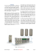


Table Of Contents
Bird Technologies Manual 7-9570-1-1(Rough Draft) 08/19/16 Page 4
Table of Contents
Overview .............................................................................................................. 7
Unpacking............................................................................................................ 8
Remote Unit ......................................................................................................... 8
Installation ........................................................................................................... 8
Location ............................................................................................................ 8
Mounting ............................................................................................................ 8
Connections ....................................................................................................... 8
RF Exposure (Exposition RF) ......................................................................... 10
Functional Block Diagram ............................................................................... 10
Operation ........................................................................................................... 11
Web Based GUI Interface ................................................................................. 12
Master Unit......................................................................................................... 14
Master Frame Unit ............................................................................................ 15
BUI (Base Station Interface Module)................................................................. 15
Functional Description..................................................................................... 16
LED Behavior.................................................................................................. 17
POI Module (Point of Interconnect Module)...................................................... 18
FOI Module (Fiber Optic Interface Module)....................................................... 18
Functional Description..................................................................................... 18
Central Gateway Computer.............................................................................. 19
Figures and Tables
Figure 1: Typical Fiber DAS System ................................................................... 7
Figure 2: Front view of the DDL Remote Radio Head ......................................... 9
Figure 3: Chassis mounting dimensions ............................................................ 10
Figure 4: DDL functional block diagram............................................................. 11
Figure 5: DDL system layout screen.................................................................. 13
Figure 6: Typical overview screen ..................................................................... 13
Figure 7: RF Status drop-down menu selection................................................. 14
Figure 8: RF Config drop-down menu selection ................................................ 15
Figure 9: Typical master unit.............................................................................. 16
Figure 10: BIU module ....................................................................................... 17
Figure 11: POI module ....................................................................................... 18
Figure 12: FOI module ....................................................................................... 19
Table 1: Operating Bands..................................................................................... 8
Table 2: DDL Specifications ................................................................................. 9
Table 3: DDL front panel LED behavior.............................................................. 12