
User's Manual


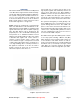


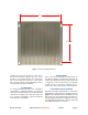
Table Of Contents

Bird Technologies Manual 7-9570-1-1(Rough Draft) 08/19/16 Page 7
OVERVIEW
This manual details the Installation and Operation
of the Bird Technologies Remote Radio Head Sys-
tem models DDL100/DDL200/DDL300/DDL400.
The system is designed to distribute wireless ser-
vice for voice and data to/from a Master Unit
located at the BTS site and to/from the Remote
Radio Heads (Remote Units) which are indoor
mounted throughout the coverage area.
Figure 1 shows an overall layout of a typical instal-
lation. The DDL Remote Unit transmits into a dis-
tributed antenna system (DAS) for downlink output
signals and a fiber optic cable for uplink output sig-
nals. The DDL Remote Unit is designed as the
peripheral part of the overall DAS network/system
and performs as a downlink transmitter and an
uplink receiver. A Fiber DAS uses fiber optic cables
to distribute RF signals from a base station to
remotely located antenna when coaxial cable
losses would be to high or it is impractical to install
coaxial cables. Fiber DAS can be used indoors to
cover large buildings where outside penetration of
RF signals is insufficient. It can also be used to
provide coverage in areas such as road tunnels,
rail tunnels, airports, metro lines, etc.
The system uses a common optical cable for its
signal paths (uplink and downlink) between the
remote units and master unit. Either WDM or
CDWM is used as the optical transmission tech-
nique. In addition, the fiber optic cable carries an
optical sub carrier which allows control signals to
pass between the maser unit and the remote units.
The system is managed by a central gateway com-
puter (CGW) that is the overall interface point for
system management functions. The CGW com-
puter is connected to the master unit and has rout-
ing, firewall functionality, alarm logging, and access
control for the complete DAS system. The remote
unit has a WEB based GUI interface that is
accessed via the CGW computer.
The Bird Technologies Fiber-DAS system consists
of two major parts including a Master Unit (MU)
which functions as the head-end and at least one
or more Remote Units which function as remote-
ends. Connection between the customers BTS and
the Master Unit (or head-end) is through coaxial
cable while the connection between the Master
Unit and Remote Units is through fiber optic cable.
Figure 1: Typical Fiber DAS system.