
User's Manual


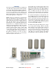


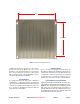
Table Of Contents

Bird Technologies Manual 7-9570-1-1(Rough Draft) 08/19/16 Page 8
UNPACKING
Each major component of the Fiber DAS system is
individually packaged and shipped via motor freight
or UPS. It is important to report any visible damage
to the carrier immediately. It is the customer's
responsibility to file damage claims with the carrier
within a short period of time after delivery (1 to 5
days).
REMOTE UNIT
The DDL Remote Unit is a high performing wide-
band remote radio head equipped with linear vari-
able gain amplifiers supporting 4 operating bands
as listed in Table 1. The lightweight, convection
cooled IP42 chassis ensures high performance in
any indoor environment. The DDL Remote Unit is
designed for indoor mounting only. One chassis
can house from one to four different operating
bands. Product model numbers reflect the number
of installed bands. DDL100 has 1 band, DDL200
has 2 bands, DDL300 has 3 bands, and DDL400
has 4 bands installed. Labels are placed on the
front panel next to the DAS RF connectors to des-
ignate the operating bands used and where to
make the proper antenna line connections. The
Remote Unit is shown in Figure 2 and specifica-
tions are listed in Table 2.
INSTALLATION
The following sub-sections of the manual discuss
general considerations for installing the Remote
Unit. All work should be performed by qualified per-
sonnel and in accordance with local codes.
Location
The layout of the antenna distribution system will
be the prime factor in determining the mounting
location of this unit. However, safety and service-
ability are also key considerations. The unit should
be located where it can not be tampered with by
the general public, yet is easily accessible to ser-
vice personnel. Also, consider the weight of the
unit and the possibility for injury if it should become
detached from its mounting for any reason.
The unit needs to be installed such that there can
be unobstructed air flow around the back of the
chassis. Insure that the heat sink fins are unob-
structed. The various subassemblies within the
equipment cabinet will stay warm during normal
operation so in the interest of equipment longevity,
avoid installation locations that carry hot exhaust
air or are continually hot.
Mounting
Figure 3 shows the mounting hole layout for the
chassis. Mount the cabinet using 3/16” (5 MM)
diameter steel bolts (not supplied). We recommend
flat washers on both ends and a lock washer under
the nut. Nut and bolt mounting is preferred to the
use of lag bolts. Use backer blocks where neces-
sary to spread the force over a larger area. In
areas of known seismic activity, additional devices
such as tether lines may be necessary.
Because Bird Technologies cannot anticipate all of
the possible mounting locations and the structure
types where these devices will be located, we rec-
ommend consulting local building inspectors, engi-
neering consultants or architects for advice on how
to properly mount objects of this type, size and
weight in your particular situation. It is the custom-
ers responsibility to make sure that these devices
are mounted safely and in compliance with building
codes.
Connections
All RF cabling connections to the booster should
be made and checked for correctness prior to pow-
ering up the system. N(f) bulkhead connectors are
Band Uplink (MHz) Downlink (MHz)
Pout (DL)
dBm/Composite
700 (LTE)
698 - 716
776 - 787
728 - 756 23
850 (CELL) 824 - 849 869 - 894 23
1900 (PCS) 1850 - 1915 1930 - 1995 23
2100 (AWS) 1710 - 1780 2110 - 2180 23
Table 1: Operating Bands.