
User Manual
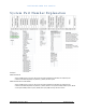
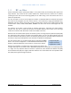
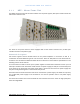
Table Of Contents
- System Part Number Explanation
- 1 Introduction
- 2 System Description
- 2.1 Master Unit
- 2.2 Remote Unit
- 3 System design
- 4 Installation guidelines
- 5 Commissioning
- 6 RF Commissioning

DELTANODE FIBER DAS MANUAL
©DeltaNode Solutions 2012
9
Revision 12-03
2.1.1 MFU – Master Frame Unit
The Master Frame Unit houses the other modules such as power supplies, fiber-optic interface cards and
base station interface units.
Figure 1: Master Unit
The frame in the picture shows a frame equipped with 3 base station interface units, 6 fiber-optic
interface cards and one power supply.
Functional description
One frame supports several modules which can be placed anywhere in the frame as well as a
combination of several different types of units in a frame. There are 16U positions in the frame that can
be utilized. The modules have different widths which can be found in each module’s specifications in the
following sections of this manual.
This means that one shelf can house up to 4 power supplies or 8 base station interface cards or up to 16
fiber-optic interface cards. Each frame needs at least one power supply, but they do not necessarily have
to be placed in the frame that they power. Quite often a system has more than one power supply and
they are usually placed together in one frame for easy access.
Each frame has two molex connectors that can be connected to a power supply. This allows for a primary
and a redundant power supply to be connected to it to ensure operation even if one power supply
should fail.
The frame also contains fans used to ventilate the units housed in the frame. These are high quality fans
that have a high MTBF.