
User's Manual
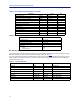
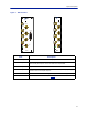
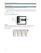
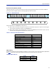
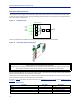
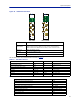
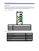
Table Of Contents
- Safety Precautions
- About This Manual
- Table of Contents
- Chapter 1 Introduction
- Chapter 2 System Description
- Chapter 3 Installation guidelines
- Chapter 4 DAS Software Configuration
- Chapter 5 Commissioning
- Chapter 6 RF Commissioning
- Chapter 7 Model Identification

FiberDistributedAntennaSystem(FiberDAS)
11
Table 5 RF and Electrical Performance of the BIU
Table 6 BIU Mechanical Specifications
BIU Indicator Operation
Therearetw
oLEDslocatedontheBIUfrontpanel.OneisthepowerLED(green),theotheristhealarmLED(red).
BothLEDsindicateanumberofstatesbydifferentflashingsequences,see
Table7
.
Inanerrorst
atethewebinterfaceshouldbeusedtochecktheactualconditionoftheBIUbuttheLEDscangivea
quickindicationonthestateoftheunit.TheLEDsarealsousefulforlocatingthephysicalunitifseveralBIUsare
installedinthesamerack.
Table 7
State ON LED ALM LED Note
Booting 2Hz Off Normalboot
Bootingstandalonemode 2Hz 2Hz Notattachedtora
ck
BootingreadofMACad
dressfailed 2Hz On Error
Starting 0,1Hz90% 0,
1Hz90% Kernelstartup
Operation 0,5Hz10% Of
f Normaloperation
Operation 0,5Hz10% 1Hz10% Mi
noralarmstate
Operation 0,5Hz10% 2Hz25% Ma
joralarmstate
Operation 0,5Hz10% On Critic
alalarmstate
Indicator Behavior
Parameter Value Unit
Downlinkattenuation Settable 10‐30±3dB
UplinkGainformodules<1000MHz Settable 10to20±3dB
UplinkGainformodules>1000MHz Settable ‐10to10±3dB
IM3performance >55 dB
Maxinputnon‐destructive >36 dBm
Highinputalarmthresholdlevel 33 dBm
Lowinputalarmthresholdlevel 10 dBm
Inputreturnloss >20 dB
ImpedanceforallRFports 50 Ω
Isola
t
ionbetweenports >60 dB
Powerconsumption <15 W
Tempe rat ure range 0‐45 °C
Parameter Value
BasestationRFports SMA,Female
Testportsuplink(ifpresent) SMA,Female
InterconnectingRFportstoICU QMA,Female
Alarmconnector(optional) DB9,Female
ModuleWidth
DBI3xx
DBI3xxC(compact)
2Slots
1slot