
User's Manual
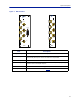
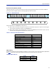
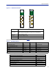
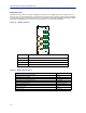
Table Of Contents
- Safety Precautions
- About This Manual
- Table of Contents
- Chapter 1 Introduction
- Chapter 2 System Description
- Chapter 3 Installation guidelines
- Chapter 4 DAS Software Configuration
- Chapter 5 Commissioning
- Chapter 6 RF Commissioning
- Chapter 7 Model Identification

SystemDescription
12
Figure 7 BIU Interfaces
BIU
ALM
ON
DL/UL BTS 1
TP UL 1
EXTERNAL
ALARM
TP UL 2
DL OUT 1
UL IN 1
DL OUT 2
UL IN 2
DL/UL BTS 2
BIU
ALM
ON
DL/UL BTS 1
TP UL 1
TP UL 2
DL OUT 1
UL IN 1
DL OUT 2
UL IN 2
DL/UL BTS 2
Item Description
Connectionfrom
theradiobasestation(RBS).
Testportforth
euplinkoftheDL/ULBTSport‐6dB.Thesignalwillbe3dBm
belowtheDL/ULBTSport.PortisnotvalidonthesimplexBIU.
Simplexdownlinkfe
edtotheFOI.
Simplexuplinkfr
omtheFOI.TheBIUwillattenuateand/oramplifythesignal
andthenroutetotheDL/ULBTSport.
Usedforex
ternalalarmmonitoring(DBI3xx,twoslotversiononly).
TheLEDsindicateva
riousstates,see
Table7
.
DL/ULBTS1/2
TPUL1/2
DLOUT1/
2
ULIN1/2
EXTE
RNALALARMS
ON
/ALMLED