
User's Manual
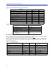
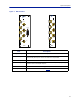
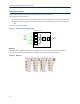
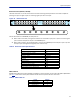
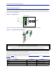
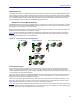
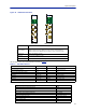
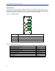
Table Of Contents
- Safety Precautions
- About This Manual
- Table of Contents
- Chapter 1 Introduction
- Chapter 2 System Description
- Chapter 3 Installation guidelines
- Chapter 4 DAS Software Configuration
- Chapter 5 Commissioning
- Chapter 6 RF Commissioning
- Chapter 7 Model Identification

SystemDescription
14
Rack-mount ICU (DIU301, DIU302)
TheRack‐moun
tICUisa1Uunitthatcontainsfourfieldscontainingsplitters/combiners.Eachfieldiscapableof
splittingoneinputintoeightoutputsorcombiningeightinputsintooneoutput.
Figure 10 Rack-mount ICU
Eachofthe4fieldshasaCOMMONportandports1‐8.
Whenusedasacombiner,thesignalstocombineareconnectedtoinputports1‐8,thesumofthesignals
(minusinsertionloss)willbeoutputontheCOMMONport.
Whenusedasasplitter,thecombinedsignalisinputontheCOMMONportandoutputonports1‐8,with
theoutputportshavingbalancedsignals(minusinsertionloss).
Table 8 Rack-mount ICU Specifications
QMA cable kit
AQMAcablekit(B
irdpartnumberDCC320)isavailableforusewiththeICU.Thekitcontains32QMAtoQMAcables
(see
Table9
)thatcanbeusedtopatchbetweentheBIUtotheICU,BIUtotheFOIorICUtoFOI.
Table 9 QMA Cable Kit
Parameter Value
Insertionloss(nominal)‐DIU301 37dB
Insertionloss(nominal)‐DIU302 21dB
Bandwidth‐DIU301 88‐2700MHz
Bandwidth‐DIU302 88‐2700MHz
OperatingTe mperature ‐25to+55C(‐13to+131F)
Impedance 50Ohm
IM3performance >50dB
Returnlossperformance >20dB
Maximumcommonportpower 20dBm
Isolationbetweenportsinsamestrip >15dB
Isolationbetweenportsindif
ferent
strips >50dB
Length Quantity
250mm(9.8”) 13
350mm(13.8”) 13
500mm(19.7”) 6