
User's Manual
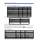
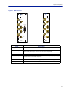
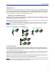
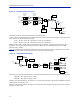
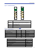
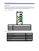
Table Of Contents
- Safety Precautions
- About This Manual
- Table of Contents
- Chapter 1 Introduction
- Chapter 2 System Description
- Chapter 3 Installation guidelines
- Chapter 4 DAS Software Configuration
- Chapter 5 Commissioning
- Chapter 6 RF Commissioning
- Chapter 7 Model Identification

FiberDistributedAntennaSystem(FiberDAS)
15
Fiber Optic Interface (FOI) unit
TheFOIconvertstheRFsignalsinthedownlinktofiber‐opticallaseroutputthatistransmittedonthefi bertothe
remoteunit.ItalsoreceivesthelaserlighttransmittedbytheRemoteUnitandconvertsitbacktoRFsignalsthatare
thenroutedtotheICUand/orBIU.
Figure 11
Base
Station
Base Station
Interface
Interconnect
Unit
Fiber-Optic
Interface Units
Fiber-Optic
Cables
to
Remote
Units
(Antenna)
Master Frame Unit
FOI
FOI
FOI
FOI
ICU
BIU
FOI Signal Flow
TheFOIispoweredfromtheMFUbackplaneandcommunicatesviaEthernetwiththeBGW.
Figure 12 Fiber Optic Interface (FOI) Unit
ThisinterfaceisdesignedtoworkwithSC‐APCconnectors(8°angledphysicalconnector)andsinglemodefibers
only.AllconnectorsbetweenthemasterunitandtheremoteunitmustbeAPC,otherwiseproblemswithreflections
willarise,whichcouldcausesevereproblemsinthesystem.
TheEt
hernetc
ommunicationbetweentheHeadendandtheRemoteUnitstakesplaceontwosub‐carriersintheFOI
wheretheEthernetsignalsaresuperimposedontheRFsignals.
Asshownin
Table10
,BirdofferstwostylesofFOIcards.The
"DOI300SeriesFOI"onpage16
andthe
"DOI401SeriesFOI"
onpa ge19
.
Table 10 FOI Variants
WARNING
Avoidlookingintoconnectedfibersandreceptacles.
ThelaserusedinthissystemisaClass3blaserthatproducesinvisibleinfra‐redcoherentlight.Notsafetoview
withopticalinstruments.Alwaysputtheprotectioncapsonunusedfibersandreceptacles.
Parameter Fiber Ports Wavelength
DOI301 2 1310nm
DOI302(WDM) 1 1310nm
DOI308x 1 variouswavelengthsavailable
DOI401 4 1550nm