
User's Manual
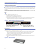
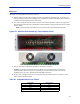
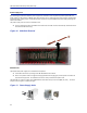
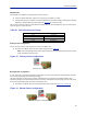
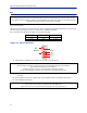
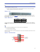
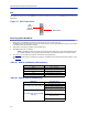
Table Of Contents
- Safety Precautions
- About This Manual
- Table of Contents
- Chapter 1 Introduction
- Chapter 2 System Description
- Chapter 3 Installation guidelines
- Chapter 4 DAS Software Configuration
- Chapter 5 Commissioning
- Chapter 6 RF Commissioning
- Chapter 7 Model Identification

FiberDistributedAntennaSystem(FiberDAS)
43
Installing Headend Equipment
Allequipmentmustbeproperlygrounded.Groundpeginthemainconnectorforbothhead‐endgear(MasterUnit)
andremotegear(RemoteUnits)mustbeconnectedtoPhase,NeutralandGroundinaproperwaybeforepoweris
connected.
Thecha
ssisof
theremoteandtherackofthemasterunitshouldbegroundedtoapotentialbarorsafetygrounding
barwhenoperated.Allelectricalinstallationsshouldbedonebyacertifiedelectricianonly.
BGW
TheBGWisdesignedtobeinstalledina19"rack.
TheBGWistypicallymounted nearthetopoftherack.
ConnectpowertoanavailableNEMA5‐15Rreceptacle.
UsinginstallerprovidedEthernetcable,connectthe“Ext”porttotheappropriateback‐haulconnection.
Theback‐haulconnectioncanbeDSL,offairmodem,LAN,WAN.SeeBGWsetupinstructions.
Figure 27
Back-haul Connection
(LAN, WAN, ETC)
Connect to Head end
Ethernet Switch, Port 25
BGW Installation, Ethernet Connections
Ethernet Switch
TheEthernetswitch,ETH,isdesignedtobeinstalledina19"rack.
PlacementistypicallybetweentheBGWandtheMasterFrameUnit.Placementconsiderationshould
includeproperroutingofEthernetcablesandtheinstallationofadditionalcablesaftertheinitial
installationiscomplete.MountingmaywithEthernetportstothefrontorrearoftherack.
ConnectpowertoanavailableNEMA5‐15Rreceptacle.
UsinginstallerprovidedEthernetcable,connectport25oftheEthernetswitchtothe“INT”portonthe
BGW.
Figure 28 Ethernet Switch