
User's Manual
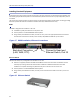
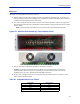
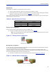
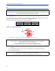
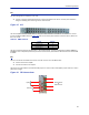
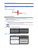
Table Of Contents
- Safety Precautions
- About This Manual
- Table of Contents
- Chapter 1 Introduction
- Chapter 2 System Description
- Chapter 3 Installation guidelines
- Chapter 4 DAS Software Configuration
- Chapter 5 Commissioning
- Chapter 6 RF Commissioning
- Chapter 7 Model Identification

FiberDistributedAntennaSystem(FiberDAS)
47
BIU
TheBIUservesastheRFinterfacebetweentheRFsourceandtheICU/FOI.EachBIUispre‐settoafrequencyband
andisnotfieldtunable.
TheBIUhastw
osetsofRFsourceconnections.Theunitscanaccepttwoindependentfeeds(withinthesameband).
ThefeedscanbefromseparatesourcesorAandBpathsinaMIMOconfiguration.
Duetothehighlev
elofRFcomingintoBIU,useonlyqualityRFcables.
Figure 34 BIU Connections
RF
Source
ICU
or
FOI
InstalltheBIUintheMasterUnit.TheBIUusestwoslotsintheMasterUnit.
Note: TheUL1andUL2uplinktestpo
rtsare3dBlowerthanthesignalonthecorrespondingDL/UL
BTSport.
ConnectSMAtotheRFsource.Tightento8in‐pounds(0.9N‐m)withacalibratedtorquewrench.
ConnectQMAtotheICU/FOI.
CAUTION
Over
drivingtheRFsourceinputintotheBIUwillcausepermanentequipmentfailureandwillvoidthewarranty.
Theinstallermustensurethatinputlevelsarenote x ceeded.PlanformaximumpoweroutoftheRFsourceand
attenuateaccordinglywithexternalattenuatorsifneeded.
BIU Type Minimum DL Input Maximum DL Input
LowLevel ‐7dBm +7dBm
HighLevel +20dBm +33dBm
CAUTION
WhenmatingRFconnectors,ensurethattheyareproperlyalignedandnotcrossthreaded.
TightenSMAconnectorsto8in.‐lbs(0.9N‐m).
DoovertorqueRFconnectors,thiscouldresultindamagetotheUnit.
DonotundertorqueRFconnectors,thiscouldresultinpoorsignaltransmission.
CAUTION
Excesstensiononth
ecab
leorconnectorsmaycausePIMissues.
Cablesmustbesecuredintherackwithoutapplyingtensiontotheconnectors.