
User's Manual
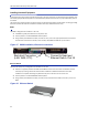
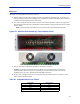
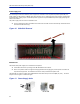
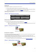
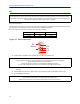
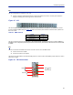
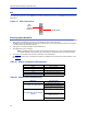
Table Of Contents
- Safety Precautions
- About This Manual
- Table of Contents
- Chapter 1 Introduction
- Chapter 2 System Description
- Chapter 3 Installation guidelines
- Chapter 4 DAS Software Configuration
- Chapter 5 Commissioning
- Chapter 6 RF Commissioning
- Chapter 7 Model Identification

Installationguidelines
48
ICU
TheICUisdesignedtobeinstalledina19"rack.
TheICUistypicallyinstalleddirectlyaboveorbelowtheMasterUnitchassis.Considerpostinstallation
changesandtestingwhenselectingaslottoinstalltheICU.
Figure 35 ICU
TheICUhasQMAconnectors.QMAcablekit‐BirdpartnumberDCC320isavailableforusewiththeICU.Thekit
contains32QMAtoQMAcables(see
Table60
)thatcanbeusedtopatchbetweentheBIUtotheICU,BIUtothe
FOIorICUtoFOI
.
Table 60 QMA Cable Kit
TheICUisconfiguredwithtwoidenticalpaths‐uplinkanddownlink.Thetypicalconfiguration[DIU301(88MHzto
2700MHz)]isfour1:8splitters/combiners(twoforULandtwoforDL).NotethatthetheoreticallossforeachDIU301
is35dBm.
FOI
TheFOIismountedintheMasterUnitchassis.TheFOIusesoneslotintheMasterUnit.
TheRFconnectionsareQMA.
ThefiberconnectionsareSC/APC.
TheFOIca
nbeorderedwithanoptionalDCC330jumperkit.ThekitcontainstwoSC/APCjumpersthatare5meters
(16.4feet)inlength.
Figure 36 FOI Connections
OPTO IN/OUT
for
Remote Units
Uplink
Downlink
Length Quantity
250mm(9.8”) 13
350mm(13.8”) 13
500mm(19.7”) 6