
User's Manual
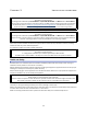
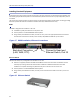
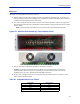
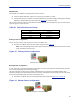
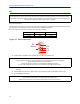
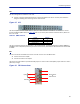
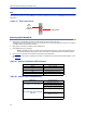
Table Of Contents
- Safety Precautions
- About This Manual
- Table of Contents
- Chapter 1 Introduction
- Chapter 2 System Description
- Chapter 3 Installation guidelines
- Chapter 4 DAS Software Configuration
- Chapter 5 Commissioning
- Chapter 6 RF Commissioning
- Chapter 7 Model Identification

FiberDistributedAntennaSystem(FiberDAS)
49
RFU
Theintegratedrepeaterunit,RFU,DMR400ismountedintheMasterUnitchassis.TheDMR400usestwoslotsinthe
MasterUnit.
Figure 37
Rebroadcast
Uplink/
Downlink
RF
Source
RFU Connections
Powering Up the Head End
1. ApplypowertotheBGWbypressingthepowerbuttonontheleftsideoftheunit.
TheBGWre
quiresapproximately5minutestocompletelybootup.DuringtheBGWbootprocess,themodules
intheMasterUnitwillflashRedandGreen.
2. ApplypowertotheEt
h
ernetSwitchandthe MasterUnit.
3. VerifyBGWbo
otcycleiscomplete,
Note: TheBGWwillha
vegreenLED'slitevenwhenpoweredoff.ThisispartoftheLANwakeupfea‐
ture.WhentheBGWisrunningtherewillbethreeLED's litandtheharddriveiconshowingactivity.
4. See
Table61
fortheLEDalarmcodesforthemodulesintheMasterUnit.
AftertheBGWbootproce
ssiscomplete,allmodulesintheMasterUnitshouldhavesomeLEDindication.Ifnot,
see
Table62
.
Table 61 Master Unit Module LED Indicators
Table 62 Master Unit Troubleshooting
Status LED Indication
Normal Green‐slowflash
IncomingAlarm SolidRed‐Limitedto5seconds
Warning RedLEDflashes1Hz1/8dutycycle
Error RedLEDflashes2Hz¼dutycycle
Critical RedLEDremainssolid
Malfunction Corrective Action
If no modules have LED indications
CheckPowercabletoPSU.
CheckpowersourceforMasterUnit.
CheckconnectionfromPSUtoChassis.
If a module does not have LED ON
Indicator
Verifythemoduleisproperlyseatedinto
thecha
ssis.
Mov
eamoduletoanotherslotonthe
MasterUnitchassis.
Replacemodule .