
User's Manual


DELTANODE USER MANUAL
©DeltaNode Solutions 2015
7
Revision 15-01
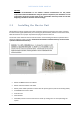
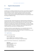
3. Connectors and connections of the RU are listed in the picture below.
Figure 6: Connector and connections on the Remote Unit
After this the fibers should be connected in the fiber optical port. This can either be done with
standard SC/APC fibers or a special heavy-duty SCRJ-cable for outdoor and rough environments (IP65
class). Antenna jumpers are connected to the N-type or DIN 7-16 connectors at the bottom, and
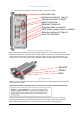
finally the power cord is connected using an IP65 protective housing (included, see picture below).
Figure 7: Mains Connector
When the power is connected the remote automatically turns on and will attempt to connect to the
master unit over the fiber.
All electrical installations should be done by an FCC Licensee or/and a certified electrician only!
After the successful mounting installation and powering the Remote units, user can now start
optimizing the DAS system and accessing the Remote units through the Base Station Gateway.
Login and access information such as username and passwords are provided separately.
Ground screw
Antenna connector, Type N
Optical connector 1 and 2
Mains Connector
Ethernet Connector
External alarm connector
LED status, green power, red fault
Antenna connector, Type N
Gore-Tex Breather
Ground
Phase
Zero