Installation, Operation and Maintenance Manual HYDROBLOC LS SERIES HEATLESS COMPRESSED AIR DRYER MODEL LS60 through LS2580 This instruction manual must be read by everyone who installs or works with this equipment Form No: X-1183 (01/2000) Printed in USA
Contents HYDROBLOC LS SERIES SPECIFICATIONS Section 1 1.1 1.2 1.2.1 1.2.2 1.2.3 1.2.4 Section 2 2.1 2.2 2.3 2.4 2.5 2.6 2.7 2.8 2.9 2.10 Section 3 3.1 3.2 3.3 3.4 3.5 3.6 3.7 3.8 General Information Foreword ............................................................................................................................... General System Information ................................................................................................. Dryer ........................................
Contents Section 4 4.1 4.2 4.3 4.4 4.5 4.6 4.7 4.8 4.9 4.10 4.11 4.12 4.13 4.14 4.15 4.16 4.17 Maintenance and Repair Preventative Maintenance Schedule .................................................................................... Weekly .................................................................................................................................. Quarterly ............................................................................................................................
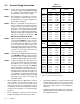
HYDROBLOC LS SERIES SPECIFICATIONS STANDARD DESIGN OPERATING CONDITIONS MODEL FLOW CAPACITY¹ (scfm) LS60 LS110 LS130 LS185 LS240 LS270 LS360 LS505 LS630 LS760 LS1000 LS1250 LS1500 LS2070 LS2580 60 110 130 185 240 270 360 505 630 760 1000 1250 1500 2070 2580 Operating Pressure Operating Temperature Inlet Moisture Content 60 psig minimum 150 psig maximum 40° F minimum 120° F maximum Saturated (at specified inlet pressure) Outlet Moisture Content -40 °F Dew Point @ line pressure ¹ Based on 100°F inle
HYDROBLOC LS SERIES SPECIFICATIONS MODEL PREFILTER AFTERFILTER LS60 LS110 LS130 LS185 LS240 LS270 LS360 LS505 LS630 LS760 LS1000 LS1250 LS1500 LS2070 LS2580 D-0100-CF D-0175-CF D-0175-CF D-0250-CF D-0250-CF D-0400-CF D-0400-CF D-0600-CF D-0600-CF D-0750-CF D-1000-CF D-1200-CF D-1500-CF D-2000-CF D-3000-CF D-0100-PF D-0100-PF D-0170-PF D-0170-PF D-0300-PF D-0300-PF D-0405-PF D-0510-PF D-0850-PF D-0850-PF D-1020-PF D-1225-CF D-1500-PF D-2000-PF D-3000-PF
1 General Information 1.1 Foreword This manual is designed to serve as the installation, operation, and maintenance guide for your dryer system. The contents of this manual should be carefully read BEFORE attempting any phase of installation, operation or maintenance. Failure to follow the operating and maintenance procedures of the instruction manual could result in personal injury or property damage.
1.2.3 Automatic Drain Valves As previously stated, the accumulated water and oil mixture collected by a prefilter must be periodically drained from the prefilter housing sump. A Deltech Automatic Drain Valve is a recommended and reliable means of removing collected moisture, oil and sludge from coalescing prefilter housings and other components requiring periodic draining. 1.2.4 Afterfilter Assembly The Deltech D-Series Particulate Afterfilter Assembly is another feature offered.
2 Installation 2.1 Receiving and Inspection Immediately upon receipt of the dryer, thoroughly inspect for damage that may have occurred during shipment. Since the dryer is shipped F.O.B. Ocala, Florida, the carrier is legally responsible for damage incurred during shipping. Shipping damage is not covered by the dryer warranty. If goods are received short or damaged, notify the carrier and insist on a notation of the loss on the face of the bill of lading.
2.4 NOTE 1: NOTE 2: NOTE 3: NOTE 4: NOTE 5: NOTE 6: 1. 2. 2-2 Table 2.1 CONNECTIONS General Piping Information Use the proper pressure rated piping, fittings and valves as approved by ASME, ANSI, ASA, etc. Separate or special requirements by local and/or municipal codes may also apply. Model The manufacturer is not liable for code violations, downtime, component failure or consequential damages to customer supplied components and/or equipment.
2.7 PREFILTER AIR INLET BLOCK VALVE Electrical Connection NOTE 1: Use proper, load-rated components as approved by NEC, NEMA, CSA, UL, etc., as required. Local and municipal codes may also apply. All installations and connections must be in accordance with recognized electrical codes in effect. NOTE 2: It is mandatory that each dryer be individually GROUNDED. Do not use your plant’s frame as a ground. Use an adequate ground with the conductor sized to NEC.
CAUTION STATIC SENSITIVE DEVICES STATIC SENSITIVE DEVICES CAN BE DAMAGED BY ELECTROSTATIC DISCHARGE. YOU CAN MINIMIZE THE CHANCES OF DESTROYING SUCH DEVICES BY: 1. KNOWING THAT THERE IS A POTENTIAL STATIC SENSITIVE PROBLEM. 2. ADHERING TO THE GUIDELINES LISTED BELOW FOR HANDLING THEM. 3. USING RECOMMENDED PACKAGING AND BENCH TECHNIQUES. FOLLOW THESE PRACTICES TO MINIMIZE DAMAGE TO STATIC SENSITIVE DEVICES. 1. DO NOT WELD ON THIS EQUIPMENT AND/OR ASSOCIATED PIPING.
CAUTION: Surges, spikes and input voltage of less than eighty-five (85) VAC or greater than one hundred and thirty-two (132) VAC, may cause the Dryer Control System to operate erratically, or malfunction. This malfunction may or may not be accompanied by an alarm. Adequate surge, spike, brownout, and blackout protection must be provided to protect your equipment and allow safe shutdown time (an uninterrupted power supply is recommended).
b) Close the dryer control system enclosure cover and tighten all cover latches. CAUTION: Do not remove the factory programmed microcomputer chip or any I.C. chip from the logic control circuit board. Improper removal will cause irreparable damage to these highly static-sensitive components. Damage to these components will render the dryer control system inoperative until replacement is accomplished by a Deltech Field Service Engineer.
When the Energy Management System LED indicator is OFF, the dryer either does not have the Compu-Save Energy Management System option, or that the sensor has determined that the relative humidity in the on-line chamber has reached the predetermined set point. At next switchover, that chamber will regenerate using purge air. When the Energy Management System LED indicator is flashing, a high humidity condition may exist or there is an Energy Management System failure.
3 Operation 3.1 How It Works Incoming air or gas is first passed through the system prefilter to remove liquid water and oil contaminants. The dryer then removes vaporous contaminants. The dryer's cycle control system alternately cycles the compressed gas flow through the unit's twin desiccant chambers. As the vapor-laden gas supply enters and flows downward through a desiccant chamber, the contaminant vapors are attracted to and adsorbed on the surface of the activated desiccant.
Do not start the dryer with compressed air flow through the dryer. Close customer supplied dryer shut-off valves before beginning start-up procedure. 1. Refer to the General Arrangement drawing as necessary for component identification and location while conducting start-up and operational procedures. Note: If your dryer cannot be started, or fails to start due to special installation or other problems, contact your local Deltech Sales Representative for assistance. 2. 3.
Afterfilter cartridges are NOT interchangeable and must be installed in their respective assemblies ONLY. The proper filter cartridge part number is listed on each Prefilter and Afterfilter Assembly. 15. Refer to Appendix A (Appendix C for -100°F pdp) of this manual and calculate your dryer model's purge pressure setting as instructed. 16. Locate the Purge Adjusting Valve. Slowly rotate dryer’s Purge Adjusting Valve until the Purge Pressure Indicator indicates the calculated purge pressure setting.
IMPORTANT: Water molecules can diffuse through a pinhole-size leak even though pressure inside the piping is several hundred PSIG. It is not uncommon to have a minute pinhole leak in a gas line cause an increase in dew point from -40°F to -10°F at a distance of forty or more feet downstream of the leak. 12. SLOWLY open the customer-supplied System Outlet Isolation Valve, while monitoring the Outlet Pressure Gauge (if dryer so-equipped).
right chamber. Both Purge Exhaust Switching Valves will close. The desiccant chambers will immediately begin pressurizing to system pressure as indicated by chamber pressure gauges. For dryers with the Hydrobloc Energy Management System: During operation in the Energy Management Mode, the off-stream chamber may remain pressurized (in ENERGY MANAGEMENT ACTIVE). If this condition is noted, proceed as follows to adjust purge pressure. 10.
5. Close any manual vent or drain valves installed in prefilter and afterfilter assemblies. 6. If the prefilter assembly utilized was factoryequipped with an automatic drain valve or drain trap, inspect for, and remove pipe plug or cap which may have been installed in drain port for shipping purposes. 7. Ensure that all associated pipe and tubing connections, flanges, unions, plugs, mounting bolts, pipe hangers, etc., have been checked tight and/or properly secured.
20. The Start-Up procedure for models LS2070 and LS2580 is now complete. Proceed to the Normal Operation Checks section of this manual for final operational checks and adjustments. 3.5 Normal Start-Up or Restart For Dryers With Fixed Cycle Electronic Timer Control 10. The Normal Start-Up or Restart procedure for models LS60 through LS1000 is now complete. Proceed to the Normal Operational Checks section of this manual for final operational checks and adjustments. 3.
chamber is pressurized, the Purge Pressure Indicator will read “system pressure”.) 12. The Normal Start-Up or Restart procedure for models LS60 through LS1000 is now complete. Proceed to the Normal Operational Checks section of this manual for final operational checks and adjustments. Dryer Models LS1250 and LS1500 13. The Normal Start-Up or Restart procedure for models LS1250 through LS1500 is now complete.
pressurized for regeneration. (When the off-line chamber is pressurized, the Purge Pressure Indicator will read “system pressure”.) 13. The Normal Start-Up or Restart procedure for models LS2070 through LS2580 is now complete. Proceed to the Normal Operational Checks section of this manual for final operational checks and adjustments. 3.7 6.
b) Close the Pilot Gas Supply Valve. c) Open the Pilot Gas Filter's Bleed Valve. Allow pilot gas system to depressurize through the Pilot Gas Filter’s Bleed Valve. When pilot gas pressure is sufficiently reduced, the Purge Exhaust Switching Valves will automatically open to depressurize dryer through Purge Exhaust Muffler. d) SLOWLY open customer supplied depressurization valve to vent the dryer internal air pressure.
4 Maintenance and Repair 4.1 Preventative Maintenance Schedule Weekly 1. Check the following operating conditions: a) Purge pressure setting (during regeneration) b) Inlet pressure c) Inlet flow rate d) Inlet temperature For optimum dryer operation and performance, these recorded parameters should correspond as close as is possible to the design operating conditions and specifications noted on the Dryer Specification Label (located on inside cover of dryer control enclosure). 2.
Annually WARNING! Ensure that the Dryer and any associated Prefilters and Afterfilters are valve isolated and fully depressurized before attempting to remove or disassemble any components or subassemblies. Failure to do so may result in serious personal injury and/or equipment damage. 1. 2. 3. 4.2 Disassemble, clean and inspect the Outlet and Purge Check Valve Assemblies. Replace all damaged or worn parts. Disassemble, clean and inspect the Inlet Switching and Purge Exhaust Switching Valves.
Table 4.1 DESICCANT REQUIREMENTS Model 9. Activated Alumina (lbs. per chamber) OPD-4 OPD-25 LS60 24 —— LS110 42 —— LS130 72 —— LS185 72 —— LS240 92 —— LS270 145 —— LS360 145 —— LS505 192 —— LS630 239 —— LS760 318 —— LS1000 416 —— LS1250 540 —— LS1500 675 —— LS2070 875 75 LS2580 1350 150 4.3 For Dryer Models LS2070 and LS2580 a) Install the specified quantity of OPD-25 (1/4" bead) desiccant. b) Level layer of OPD-25.
5. Remove the filter cover. 6. Unscrew and remove cartridge retaining seal nuts. 7. Remove the used element cartridges. Discard the cartridges in accordance with applicable regulations. Used elements typically hold contaminants, such as compressor lubricants and particulate matter. 8. Insert new element cartridges in filter. LIGHTLY lubricate the housing O-ring with a petroleum-based lubricant that is compatible with your application. 9. Reinstall element seal nuts.
ized. DO NOT continue to remove the bowl until the filter has been completely vented to atmospheric pressure. CAUTION: Filter bowls may be heavy. Caution should be taken when removing the bowl. 4. Remove the bottom bowl by unscrewing it from the head. A strap wrench may be needed. 5. Remove the nut from the bottom of the bowl. 6. Turn the bowl upside down. 7. Inspect the drain for damage. Replace if necessary or clean with a mild soap and water.
WARNING! Ensure that the Dryer is de-energized, valve isolated, and fully depressurized before attempting to remove or disassemble any Dryer component or subassembly. Failure to do so may result in serious personal injury and/or equipment damage. 3. Remove hose that connects the drain valve to the filter. 4. Remove screw and washer from front of drain valve. 5. Remove the power supply connector and gasket (with the timer assembly, if attached) from the solenoid coil housing.
4.6 4. Moisture Indicator Recharging Procedure Remove porous disc [4] and clean sight dome. (see following CAUTION.) CAUTION: Sight Dome [2] is an acrylic plastic. Do Not clean with any type of solvent. Note: Dryer shutdown is not necessary to perform the following procedure and can be accomplished without removing the entire assembly. 5. Replace O-ring [9], and re-install screw [6] in sight dome [2]. 1. 6. Carefully pour new granular indicator into sight dome [2]. Slide porous disc [4] into place.
4.7 Inlet and Purge Exhaust Switching Valve Maintenance (LS60 through LS760) WARNING! Ensure that the Dryer is de-energized, valve isolated, and fully depressurized before attempting to remove or disassemble any Dryer component or subassembly. Failure to do so may result in serious personal injury and/or equipment damage. 1. Clean and inspect all valve hardware upon disassembly. Replace locknuts [13] and [16] and compression springs [2] and [3].
NOTE: 1. When the unit is located in a corrosive environment, coat sockethead cap screws with a corrosion resistant compound. 17 10 13 7 3 4 10 23 1 22 9 11 23 16 15 5 23 21 23 20 12 18 6 14 2 19 15 23 8 22 23 6 3 18 7 12 13 23 10 21 23 5 16 11 9 1 10 17 4 Figure 4.
4.8 Inlet and Purge Exhaust Switching Valve Maintenance (LS1000) WARNING! Ensure that the Dryer is de-energized, valve isolated, and fully depressurized before attempting to remove or disassemble any Dryer component or subassembly. Failure to do so may result in serious personal injury and/or equipment damage. 1. Clean and inspect all valve hardware upon disassembly. Replace all software and any hardware which appears damaged or abnormally worn. 2.
NOTE: 1. When the unit is located in a corrosive environment, coat sockethead cap screws with a corrosion resistant compound. 18 3 16 11 13 19 14 4 21 16 20 22 17 14 16 5 16 7 6 8 15 12 1 16 10 17 12 10 9 4 14 18 19 13 11 16 2 6 16 5 16 14 22 21 20 Figure 4.
4.9 3" Inlet Switching Valve Maintenance (Models LS1250 and LS1500) WARNING! Ensure that the dryer is de-energized, valve isolated, and fully depressurized before attempting to remove or disassemble any dryer component or subassembly. Failure to do so may result in serious personal injury and/or equipment damage. Note: Removal of valve body [21] from the dryer manifold is not required unless replacement of O-rings [23] or valve body is necessary. 1. Clean and inspect all valve hardware upon disassembly.
NOTE: 1. When the unit is located in a corrosive environment, coat sockethead cap screws with a corrosion resistant compound. 1 2 3 4 5 6 7 8 9 10 11 16 12 8 13 17 14 15 10 8 21 22 23 16 18 15 10 11 10 14 19 20 Figure 4.
4.10 2" Purge Exhaust Switching Valve Maintenance (Model LS1250 only) WARNING! Ensure that the Dryer is de-energized, valve isolated, and fully depressurized before attempting to remove or disassemble any Dryer component or subassembly. Failure to do so may result in serious personal injury and/or equipment damage. Note: Removal of valve body [16] from the dryer manifold is not required unless replacement of square O-rings [17] or valve body is necessary.
NOTE: 1. When the unit is located in a corrosive environment, coat sockethead cap screws with a corrosion resistant compound. 16 15 14 13 12 11 10 9 8 7 3 6 5 4 3 2 18 1 16 17 Figure 4.
4.11 3" Purge Exhaust Switching Valve Maintenance (Model LS1500 only) WARNING! Ensure that the dryer is de-energized, valve isolated, and fully depressurized before attempting to remove or disassemble any dryer component or subassembly. Failure to do so may result in serious personal injury and/or equipment damage. Note: Removal of valve body [18] from the dryer manifold is not required unless replacement of O-rings [19] or valve body is necessary.
NOTE: 1. When the unit is located in a corrosive environment, coat sockethead cap screws with a corrosion resistant compound. 1 2 3 4 5 6 7 9 8 10 11 12 13 14 10 15 16 8 18 17 19 20 Figure 4.
4.12 Purge and Outlet Check Valve Maintenance (Models LS60 through LS760) WARNING! Ensure that the dryer is de-energized, valve isolated, and fully depressurized before attempting to remove or disassemble any dryer component or subassembly. Failure to do so may result in serious personal injury and/or equipment damage. Note: The purge orifice [15] is specifically sized and drilled for your dryer.
NOTE: 1. When the unit is located in a corrosive environment, coat items (2) and (3) with a corrosion resistant compound. 2. Torque 1/4 - 20 screws to 40 in-lbs. Torque 5/16 - 18 screws to 135 in-lbs. 4 6 13 3 11 10 14 12 8 1 7 9 15 5 2 Figure 4.
4.13 3" Purge and Outlet Check Valve Maintenance (Models LS1000 through LS1500) WARNING! Ensure that the Dryer is de-energized, valve isolated, and fully depressurized before attempting to remove or disassemble any Dryer component or subassembly. Failure to do so may result in serious personal injury and/or equipment damage. Note: The purge orifice [4] is specifically sized and drilled for your dryer.
NOTE: 1. When the unit is located in a corrosive environment, coat items (13) and (14) with a corrosion resistant compound. 2. Torque 5/16 - 18 screws to 135 in-lbs. Torque 3/8 - 16 screws to 245 in-lbs. 16 12 17 6 14 1 15 18 12 5 11 10 7 8 4 9 3 2 19 13 Figure 4.
4.14 Remote Flow Restrictor Maintenance (Model LS1250 only) WARNING! Ensure that the dryer is de-energized, valve isolated, and fully depressurized before attempting to remove or disassemble any dryer component or subassembly. Failure to do so may result in serious personal injury and/or equipment damage. Purge Exhaust 1. Remove muffler as follows: a) Provide adequate support for muffler and flow restrictor assembly. Remove flow restrictor assembly from lower flange by equally loosening flange bolts.
4.15 Flow Restrictor Maintenance FLOW RESTRICTOR ASSEMBLY (Models LS1500 through LS2580) Item WARNING! Ensure that the dryer and any associated prefilters and afterfilters are valve isolated and fully depressurized before attempting to remove or disassemble any components or subassemblies. Failure to do so may result in serious personal injury and/or equipment damage. 1 2 3 4 5 6 Description Total Valve Body Actuator Subassembly Valve Flange O-Ring Hex Nut Threaded Stud 1 1 1 2 8 4 1.
DISASSEMBLY/ASSEMBLY INSTRUCTIONS ACTUATOR SUBASSEMBLY Item 2A 2B 2C 2D 2E 2F 2G 2H 2J 2K 2L 2M 2N Description Total Valve Flange Shaft Subassembly Spacer Mounting Plate Vibration Pad Retaining Plate Sockethead Cap Screw Lockwire Shaft Guide Compression Spring Spring Retainer Slotted Nut Cotter Pin ACTUATOR SUBASSEMBLY 1 1 4 1 1 1 4 1 1 1 1 1 1 1. Disassemble/Build the actuator subassembly in the order shown by the Actuator Subassembly Diagram (Figure 4.15).
2. Adjust orifice stroke. DETAIL 'C' A) Invert the actuator subassembly and place in a vice as shown in Detail C. B) Gently press the flange to the orifice. C) Tighten the nut until the spring retainer slightly contacts the shaft guide. D) Continue tightening nut for an additional 1/2 turn. E) Remove subassembly from the vice. Install the cotter pin. PRESSURE CONTACT Note: Orifice stroke adjustment is critical to the operation of the flow restrictor.
4.16 Purge Adjusting Valve (Models LS2070 and LS2580) WARNING! Ensure that the dryer is de-energized, valve isolated and fully depressurized before attempting to remove or disassemble any dryer component or subassembly. Failure to do so may result in serious personal injury and/or equipment damage. Note: Removal of valve body [4] is not required unless replacement of valve body is necessary. 1. Clean and inspect all valve hardware upon disassembly.
4.17 Pilot Gas Filter Maintenance (Models LS2070 and LS2580) WARNING! Ensure that the dryer is de-energized, valve isolated, and fully depressurized before attempting to remove or disassemble any dryer component or subassembly. Failure to do so may result in serious personal injury and/or equipment damage. Note: Flow through filter assembly is from outside of filter cartridge to the inside (center). 1. Clean and inspect all hardware upon disassembly.
5 Troubleshooting Guide WARNING! Ensure that the Dryer and any associated Prefilters and Afterfilters are valve isolated and fully depressurized before attempting to remove or disassemble any subassemblies or components. Failure to do so may result in serious personal injury and/or equipment damage. WARNING! Some of the following troubleshooting checks require entering the Dryer Control System enclosure while the Dryer’s Electrical Power Supply is energized.
PROBLEM/POSSIBLE CAUSE CHECKS AND REMEDY 4. Inlet gas temperature is above the dryer’s design inlet temperature specified on the Dryer Specification Label located on the inside cover of the dryer system control enclosure. 4. Check the compressor aftercooler and cooling system. Adjust as necessary to bring the dryer inlet temperature to design specification. 5. Liquids entering the dryer inlet. 5. Isolate and depressurize Prefilter Assembly.
PROBLEM/POSSIBLE CAUSE CHECKS AND REMEDY Back pressure on a desiccant chamber during the regeneration cycle. (Chamber’s pressure gauge indicates above zero (0) PSIG. Note: The presence of back pressure will result in insufficient regeneration followed by dew point degradation. An off-stream chamber’s pressure gauge MUST indicate zero (0) PSIG throughout all regeneration cycles. 1.
PROBLEM/POSSIBLE CAUSE CHECKS AND REMEDY Excessive pressure drop across dryer. 1. Badly broken, dusted or fouled desiccant. 1. Shutdown and Depressurize Dryer. Inspect desiccant through fill ports and replace if badly broken, dusted or fouled. Note: If the “normally white” desiccant is fouled or discolored, inspect prefilter cartridges and drain valve or trap. 2.
PROBLEM/POSSIBLE CAUSE CHECKS AND REMEDY b) For Models LS1500 through LS2580 WARNING! Removal of the Flow restrictor should not be done unless the piping to the Purge Exhaust Muffler is adequately supported. Failure to do so may result in serious personal injury and/or equipment damage. 1. Remove Flow Restrictor from the line and refer to the Flow Restrictor Maintenance Procedure. 2. Disassemble, clean, inspect and adjust as required. Replace all worn or damaged parts as noted.
PROBLEM/POSSIBLE CAUSE CHECKS AND REMEDY 4. During Repressurization Cycle. Purge Exhaust Switching Valve has failed to close due to fouled or worn valve internals. 4. Check for pilot gas pressure at on-stream chamber exhaust valve’s pilot tubing connection. If pilot pressure is present, Shutdown and Depressurize Dryer. Disassemble, clean and inspect the Switching Valve. Replace all worn or damaged parts as noted. Valve Failure Alarm with excessive pressure exhausting through muffler.
PROBLEM/POSSIBLE CAUSE CHECKS AND REMEDY High Humidity Warning Note: A High Humidity Warning will ALWAYS cause the control system to automatically shift to fixed cycle operation. 1. Compu-Save Sensor has sensed a moisture overload condition within a desiccant bed due to the presence of one (or both) of the following conditions: 1a. Inlet flow rate (SCFM) is above dryer’s design inlet flow rate, as specified on the Dryer Specification Label located on the inside cover of the dryer system control enclosure.
PROBLEM/POSSIBLE CAUSE CHECKS AND REMEDY 4. Off-stream chamber’s Inlet Switching Valve or on-stream chamber’s Purge Exhaust Switching Valve seat is worn, damaged or fouled (allowing slight pressure leakage to enter regenerating chamber). 4. Shutdown and Depressurize Dryer. Refer to the Inlet Switching Valve and Purge Exhaust Switching Valve Maintenance procedures which are applicable to your specific dryer model.
PROBLEM/POSSIBLE CAUSE CHECKS AND REMEDY Automatic drain valve continually discharging or venting. 1. Clogged diaphragm. 1. Clean diaphragm. 2. Short in electrical component. 2. Check and replace connector or timer assembly. Automatic drain valve not discharging. 1. No electrical power. 1. Check and correct power supply and connections. 2. Timer malfunction. 2. Replace timer assembly. 3. Solenoid coil malfunction. 3. Replace solenoid coil. 4. Clogged ports. 4. Clean ports.
Appendix A Purge Curves
A-2 Purge Curves
HYDROBLOC LS SERIES PURGE CURVES Calculation of Purge Pressure Setting 1. Determine air pressure (psig) at the dryer inlet. 2. Refer to Table A-1. Determine the inlet airflow for your model and inlet air pressure. 3. To calculate purge flow consumption on the critical orifice curve: Inlet Flow (SCFM) × 14.7 PSIG Inlet Pressure (PSIG) + 14.7 PSIG 6. Note: The purge pressure can only be read and adjusted when an off-line desiccant chamber has depressurized for regeneration.
HYDROBLOC LS SERIES PURGE CURVES Orifice Dia. Gas: Temp: CD: P1 .129 Air 100°F .65 100 90 PURGE PRESSURE P1 PSIG 80 70 60 50 40 30 20 10 0 4 5 6 7 8 9 10 11 12 PURGE GAS FLOW RATE (SCFM) Figure A.
HYDROBLOC LS SERIES PURGE CURVES Orifice Dia. Gas: Temp: CD: P1 .156 Air 100°F .65 100 90 PURGE PRESSURE P1 PSIG 80 70 60 50 40 30 20 10 0 4 6 8 10 12 14 16 18 20 22 24 26 PURGE GAS FLOW RATE (SCFM) Figure A.
HYDROBLOC LS SERIES PURGE CURVES Orifice Dia. Gas: Temp: CD: P1 .172 Air 100°F .65 100 90 PURGE PRESSURE P1 PSIG 80 70 60 50 40 30 20 10 0 6 8 10 12 14 16 18 20 22 PURGE GAS FLOW RATE (SCFM) Figure A.
HYDROBLOC LS SERIES PURGE CURVES Orifice Dia. Gas: Temp: CD: P1 .203 Air 100°F .65 100 90 PURGE PRESSURE P1 PSIG 80 70 60 50 40 30 20 10 0 10 15 20 25 30 35 PURGE GAS FLOW RATE (SCFM) Figure A.
HYDROBLOC LS SERIES PURGE CURVES Orifice Dia. Gas: Temp: CD: P1 .257 Air 100°F .65 100 90 PURGE PRESSURE P1 PSIG 80 70 60 50 40 30 20 10 0 10 15 20 25 30 35 40 45 50 PURGE GAS FLOW RATE (SCFM) Figure A.
HYDROBLOC LS SERIES PURGE CURVES Orifice Dia. Gas: Temp: CD: P1 .272 Air 100°F .65 100 90 PURGE PRESSURE P1 PSIG 80 70 60 50 40 30 20 10 0 15 20 25 30 35 40 45 50 55 60 65 70 PURGE GAS FLOW RATE (SCFM) Figure A.
HYDROBLOC LS SERIES PURGE CURVES Orifice Dia. Gas: Temp: CD: P1 .290 Air 100°F .65 100 90 PURGE PRESSURE P1 PSIG 80 70 60 50 40 30 20 10 0 25 30 35 40 45 50 55 60 65 PURGE GAS FLOW RATE (SCFM) Figure A.
HYDROBLOC LS SERIES PURGE CURVES Orifice Dia. Gas: Temp: CD: P1 .359 Air 100°F .65 100 90 PURGE PRESSURE P1 PSIG 80 70 60 50 40 30 20 10 0 20 30 40 50 60 70 80 90 100 110 120 130 PURGE GAS FLOW RATE (SCFM) Figure A.
HYDROBLOC LS SERIES PURGE CURVES Orifice Dia. Gas: Temp: CD: P1 .375 Air 100°F .65 100 90 PURGE PRESSURE P1 PSIG 80 70 60 50 40 30 20 10 0 30 40 50 60 70 80 90 100 110 PURGE GAS FLOW RATE (SCFM) Figure A.
HYDROBLOC LS SERIES PURGE CURVES Orifice Dia. Gas: Temp: CD: P1 .438 Air 100°F .65 100 90 PURGE PRESSURE P1 PSIG 80 70 60 50 40 30 20 10 0 60 70 80 90 100 110 120 130 140 150 160 170 PURGE GAS FLOW RATE (SCFM) Figure A.
HYDROBLOC LS SERIES PURGE CURVES Orifice Dia. Gas: Temp: CD : P1 .563 Air 100°F .65 100 90 PURGE PRESSURE P1 PSIG 80 70 60 50 40 30 20 10 0 40 60 80 100 120 140 160 180 200 PURGE GAS FLOW RATE (SCFM) Figure A.
HYDROBLOC LS SERIES PURGE CURVES Orifice Dia. Gas: Temp: CD: P1 .688 Air 100°F .65 100 90 PURGE PRESSURE P1 PSIG 80 70 60 50 40 30 20 10 0 75 100 125 150 175 200 225 250 275 300 325 350 PURGE GAS FLOW RATE (SCFM) Figure A.
HYDROBLOC LS SERIES PURGE CURVES Orifice Dia. Gas: Temp: CD : P1 .750 Air 100°F .65 110 100 PURGE PRESSURE P1 PSIG 90 80 70 60 50 40 30 20 10 100 150 200 250 300 350 400 450 500 PURGE GAS FLOW RATE (SCFM) Figure A.
Appendix B Replacement Parts Replacement Parts B-1
HYDROBLOC LS REPLACEMENT PARTS Description Quantity Required* Model LS60 Model LS110 Model LS130 Model LS185 Model LS240 Muffler 1 1283853 1283853 1283853 1283853 1283853 Relief Valve 1 1124704 1124704 1124704 1124704 1124704 Pressure Gauge 3 1125546 1125546 1125546 1125546 1125546 AQUADEX® Repair Kit 1 1207278 1207278 1207278 1207278 1207278 Inlet/Exhaust Valve Packing Kit 1 1283204 1283204 1283214 1283214 1283222 Purge Valve Packing Kit 1 1283207 1283207 12832
HYDROBLOC LS REPLACEMENT PARTS Description Quantity Required* Model LS270 Model LS360 Model LS505 Model LS630 Model LS760 Muffler 1 1283853 1283853 1283285 1283285 1283285 Relief Valve 1 1124704 1124704 1124704 1124704 1124704 Pressure Gauge 3 1125546 1125546 1125546 1125546 1125546 AQUADEX® Repair Kit 1 1207278 1207278 1207278 1207278 1207278 Inlet/Exhaust Valve Packing Kit 1 1283225 1283225 1283227 1283229 1283231 Purge Valve Packing Kit 1 1283233 1283233 1283
HYDROBLOC LS REPLACEMENT PARTS Description Quantity Required* Model LS1000 Model LS1250 Model LS1500 Model LS2070 Model LS2580 Muffler 1 1283853 1283853 1283853 1283853 1283853 Relief Valve 1 1124704 1124704 1124704 1124704 1124704 Pressure Gauge 3 1125546 1125546 1125546 1125546 1125546 AQUADEX® Repair Kit 1 1207278 1207278 1207278 1207278 1207278 Inlet/Exhaust Valve Packing Kit 1 1272497 Inlet Valve Packing Kit 2 1256169 1256169 1252986 1252985 Exhaust Valve Pac
Appendix C Specifications, Purge Curves and Replacement Parts for -100°F Pressure Dew Doint Dryers
C-2 Specifications, Purge Curves and Replacement Parts for -100°F Pressure Dew Doint Dryers
HYDROBLOC LSC SPECIFICATIONS STANDARD DESIGN OPERATING CONDITIONS MODEL FLOW CAPACITY¹ (scfm) LSC60 36 LSC110 66 LSC130 LSC185 78 111 LSC240 LSC270 144 162 LSC360 216 Inlet Moisture Content LSC505 LSC630 303 378 Outlet Moisture Content LSC760 LSC1000 456 600 LSC1250 750 LSC1500 LSC2070 900 1242 LSC2580 1548 Operating Pressure 60 psig minimum 150 psig maximum Operating Temperature 40° F minimum 120° F maximum Saturated (at specified inlet pressure) -100 °F Dew Point @ line pressure
HYDROBLOC LSC SPECIFICATIONS C-4 MODEL LSC60 PREFILTER D-0050-CF AFTERFILTER D-0050-PF LSC110 LSC130 D-0100-CF D-0100-CF D-0100-PF D-0100-PF LSC185 D-0175-CF D-0100-PF LSC240 LSC270 D-0175-CF D-0175-CF D-0170-PF D-0170-PF LSC360 LSC505 D-0250-CF D-0400-CF D-0300-PF D-0300-PF LSC630 D-0400-CF D-0405-PF LSC760 LSC1000 D-0600-CF D-0750-CF D-0510-PF D-0850-PF LSC1250 LSC1500 D-1000-CF D-1500-CF D-0850-CF D-1500-PF LSC2070 D-2000-CF D-2000-PF LSC2580 D-3000-CF D-3000-PF Specificat
HYDROBLOC LSC PURGE CURVES Calculation of Purge Pressure Setting 1. Determine air pressure (psig) at the dryer inlet. 2. Refer to Table C-1. Determine the inlet airflow for your model and inlet air pressure. 3. To calculate purge flow consumption on the critical orifice curve: Inlet Flow (SCFM) × 14.7 PSIG Inlet Pressure (PSIG) + 14.7 PSIG 6. Note: The purge pressure can only be read and adjusted when an off-line desiccant chamber has depressurized for regeneration.
HYDROBLOC LSC PURGE CURVES Orifice Dia. Gas: Temp: CD: P1 .094 Air 100°F .65 100 90 PURGE PRESSURE P1 PSIG 80 70 60 50 40 30 20 10 0 2.5 3 3.5 4 4.5 5 5.5 6 6.5 7 PURGE GAS FLOW RATE (SCFM) Figure C.1 — Critical Orifice Calibration Curve (LSC60) C-6 Specifications, Purge Curves and Replacement Parts for -100°F Pressure Dew Doint Dryers 7.
HYDROBLOC LSC PURGE CURVES Orifice Dia. Gas: Temp: CD: P1 .129 Air 100°F .65 100 90 PURGE PRESSURE P1 PSIG 80 70 60 50 40 30 20 10 0 4 5 6 7 8 9 10 11 12 13 14 15 PURGE GAS FLOW RATE (SCFM) Figure C.
HYDROBLOC LSC PURGE CURVES Orifice Dia. Gas: Temp: CD : P1 .156 Air 100°F .65 100 90 PURGE PRESSURE P1 PSIG 80 70 60 50 40 30 20 10 0 4 6 8 10 12 14 16 18 20 22 PURGE GAS FLOW RATE (SCFM) Figure C.
HYDROBLOC LSC PURGE CURVES Orifice Dia. Gas: Temp: CD: P1 .172 Air 100°F .65 100 90 PURGE PRESSURE P1 PSIG 80 70 60 50 40 30 20 10 0 6 8 10 12 14 16 18 20 22 24 26 28 PURGE GAS FLOW RATE (SCFM) Figure C.
HYDROBLOC LSC PURGE CURVES Orifice Dia. Gas: Temp: CD: P1 .203 Air 100°F .65 100 90 PURGE PRESSURE P1 PSIG 80 70 60 50 40 30 20 10 0 10 15 20 25 30 PURGE GAS FLOW RATE (SCFM) Figure C.
HYDROBLOC LSC PURGE CURVES Orifice Dia. Gas: Temp: CD: P1 .257 Air 100°F .65 100 90 PURGE PRESSURE P1 PSIG 80 70 60 50 40 30 20 10 0 10 15 20 25 30 35 40 45 50 55 60 65 PURGE GAS FLOW RATE (SCFM) Figure C.
HYDROBLOC LSC PURGE CURVES Orifice Dia. Gas: Temp: CD: P1 .290 Air 100°F .65 100 90 PURGE PRESSURE P1 PSIG 80 70 60 50 40 30 20 10 0 25 30 35 40 45 50 55 60 65 70 PURGE GAS FLOW RATE (SCFM) Figure C.
HYDROBLOC LSC PURGE CURVES Orifice Dia. Gas: Temp: CD: P1 .313 Air 100°F .65 100 90 PURGE PRESSURE P1 PSIG 80 70 60 50 40 30 20 10 0 0 10 20 30 40 50 60 70 80 90 100 110 PURGE GAS FLOW RATE (SCFM) Figure C.
HYDROBLOC LSC PURGE CURVES Orifice Dia. Gas: Temp: CD: P1 .359 Air 100°F .65 100 90 PURGE PRESSURE P1 PSIG 80 70 60 50 40 30 20 10 0 20 30 40 50 60 70 80 90 100 PURGE GAS FLOW RATE (SCFM) Figure C.
HYDROBLOC LSC PURGE CURVES Orifice Dia. Gas: Temp: CD: P1 .406 Air 100°F .65 100 90 PURGE PRESSURE P1 PSIG 80 70 60 50 40 30 20 10 0 20 30 40 50 60 70 80 90 100 PURGE GAS FLOW RATE (SCFM) Figure C.
HYDROBLOC LSC PURGE CURVES Orifice Dia. Gas: Temp: CD : P1 .500 Air 100°F .65 100 90 PURGE PRESSURE P1 PSIG 80 70 60 50 40 30 20 10 0 0 20 40 60 80 100 120 140 160 PURGE GAS FLOW RATE (SCFM) Figure C.
HYDROBLOC LSC PURGE CURVES Orifice Dia. Gas: Temp: CD: P1 .563 Air 100°F .65 100 90 PURGE PRESSURE P1 PSIG 80 70 60 50 40 30 20 10 0 40 60 80 100 120 140 160 180 200 PURGE GAS FLOW RATE (SCFM) Figure C.
HYDROBLOC LSC PURGE CURVES Orifice Dia. Gas: Temp: CD : P1 .688 Air 100°F .65 100 90 PURGE PRESSURE P1 PSIG 80 70 60 50 40 30 20 10 0 75 100 125 150 175 200 225 250 275 300 PURGE GAS FLOW RATE (SCFM) Figure C.
HYDROBLOC LSC REPLACEMENT PARTS Description Quantity Required* Model LSC60 Model LSC110 Model LSC130 Model LSC185 Model LSC240 Muffler 1 1283853 1283853 1283853 1283853 1283853 Relief Valve 1 1124704 1124704 1124704 1124704 1124704 Pressure Gauge 3 1125546 1125546 1125546 1125546 1125546 AQUADEX® Repair Kit 1 1207278 1207278 1207278 1207278 1207278 Inlet/Exhaust Valve Packing Kit 1 1283204 1283204 1283214 1283214 1283222 Purge Valve Packing Kit 1 1283207 1283207
HYDROBLOC LSC REPLACEMENT PARTS Description Quantity Required* Model LSC270 Model LSC360 Model LSC505 Model LSC630 Model LSC760 Muffler 1 1283853 1283853 1283285 1283285 1283285 Relief Valve 1 1124704 1124704 1124704 1124704 1124704 Pressure Gauge 3 1125546 1125546 1125546 1125546 1125546 AQUADEX® Repair Kit 1 1207278 1207278 1207278 1207278 1207278 Inlet/Exhaust Valve Packing Kit 1 1283225 1283225 1283227 1283229 1283231 Purge Valve Packing Kit 1 1283233 1283233
HYDROBLOC LSC REPLACEMENT PARTS Description Quantity Required* Model LS1000 Model LS1250 Model LS1500 Model LS2070 Model LS2580 Muffler 1 1283853 1283853 1283853 1283853 1283853 Relief Valve 1 1124704 1124704 1124704 1124704 1124704 Pressure Gauge 3 1125546 1125546 1125546 1125546 1125546 AQUADEX® Repair Kit 1 1207278 1207278 1207278 1207278 1207278 Inlet/Exhaust Valve Packing Kit 1 1272497 Inlet Valve Packing Kit 2 1256169 1256169 1252986 1252985 Exhaust Valve Pa
DELTECH A United Dominion Company Flair Engineered Products 4647 SW 40th Avenue • Ocala, FL 34474-5799 Telephone 352-873-5700 • Fax 352-873-5744 WEB ADDRESS: www.udi-flair.com/deltech E-MAIL: deltech@udi-flair.com U.S. FACILITIES New Castle, Delaware Ocala, Florida Stanley, North Carolina CANADIAN FACILITIES Brockville, Ontario Tel.