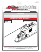
1-05 BH20030, Rev 0 DOING OUR BEST TO PROVIDE YOU THE BEST DA66B BRAKE ACTUATOR OPERATORS MANUAL READ complete manual CAREFULLY BEFORE attempting operation. ASSEMBLY CALIBRATION OPERATION REPLACEMENT PARTS DEMCO • Dethmers Mfg. Co. • 4010 320th St. • P.O. Box 189 • Boyden, IA 51234 PH: (712) 725-2311 • Toll Free: 1-800-543-3626 • FAX: 1-800-845-6420 www.demco-products.
DEMCO MODEL DA66B ACTUATOR Model DA66B is a hydraulic surge brake actuator for trailers with two or four wheels. When brakes are applied on the towing vehicle, forward inertia of trailer toward towing vehicle applies brakes on trailer in direct relation to manner brakes are applied on towing vehicle. Brake towing vehicle hard and brakes on trailer are applied hard. Master cylinder push rod spring assembly protects system from hydraulic pressure overload.
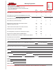
Warranty Registration Dethmers Manufacturing Company 4010 320th Street • Box 189 • Boyden, Iowa 51234 Toll Free 800-54DEMCO (800-543-3626) • FAX 800-845-6420 www.demco-products.
Postage Dethmers Manufacturing Company 4010 320th Street, Box 189 Boyden, Iowa 51234 Page 4
SAFETY TAKE NOTE! THIS SAFETY ALERT SYMBOL FOUND THROUGHOUT THIS MANUAL IS USED TO CALL YOUR ATTENTION TO INSTRUCTIONS INVOLVING YOUR PERSONAL SAFETY AND SAFETY OF OTHERS. FAILURE TO FOLLOW THESE INSTRUCTIONS CAN RESULT IN INJURY OR DEATH. THIS SYMBOL MEANS ATTENTION BECOME ALERT YOUR SAFETY IS INVOLVED! SIGNAL WORDS Note use following signal words DANGER, WARNING, and CAUTION with safety messages.
SAFETY...YOU CAN LIVE WITH IT EQUIPMENT SAFETY GUIDELINES Every year many accidents occur which could have been avoided by a few seconds of thought and a more careful approach to handling equipment. You the operator, can avoid many accidents by observing and following precautions in this section. To avoid personal injury, study the following precautions and insist those working with you, or you yourself, follow them.
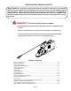
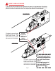
SAFETY SIGN LOCATIONS Types of safety sign and locations on equipment are shown in illustration below. Good safety requires that you familiarize yourself with various safety signs, type of warning, and area or particular function related to that area, that requires your SAFETY AWARENESS. DRUM BRAKES This decal is located in the position shown on both sides of the actuator. The replacement part number for two decals is BH21004. Preset Fasteners DO NOT adjust without factory specifications.
SAFETY SIGN CARE • Keep safety signs clean and legible at all times. • Replace safety signs that are missing or have become illegible. • Replacement parts that displayed a safety sign should also display safety sign. • Safety signs are available from your distributor, dealer parts department, or factory. How to install safety signs: • Be sure that installation area is clean and dry. • Decide on exact position before you remove backing paper. • Remove smallest portion of split backing paper.
BEFORE OPERATION: • Carefully review and follow the installation instructions on page 16 of this manual. • Carefully study and understand this manual. • Always wear protective clothing and substantial shoes. • Give equipment a visual inspection for any loose bolts, worn parts, or cracked welds, and make necessary repairs. Follow maintenance safety instructions included in this manual. • Be sure there are no tools lying on or in equipment.
• Beware of bystanders, PARTICULARLY CHILDREN! Always look around to make sure it is safe to start engine of towing vehicle or move equipment. This is particularly important with higher noise levels, as you may not hear people shouting. • NO PASSENGERS ALLOWED- Do not carry passengers anywhere on or in equipment. • Do not clean, lubricate, or adjust your equipment while it is moving. • When halting operation, even periodically, set towing vehicles parking brake, shut off engine, and remove the ignition key.
FOLLOWING OPERATION • Following operation, or when unhitching, stop towing vehicle, set brakes, shut off the engine and remove ignition key. • Store unit in an area away from human activity. • Do not permit children to play on or around stored unit. • Make sure all parked units are on a hard, level surface and engage all safety devices. • Wheel chocks may be needed to prevent unit from rolling.
• Watch for obstructions overhead and side to side while transporting. • Always operate equipment in a position to provide maximum visibility at all times. Make allowances for increased length and weight of equipment when making turns and/or stopping. PERFORMING MAINTENANCE • Carefully review and follow the maintenance instructions on page 17 of this manual. • Good maintenance is your responsibility. Poor maintenance is an invitation to trouble. • Make sure there is plenty of ventilation.
BOLT TORQUE TORQUE DATA FOR STANDARD NUTS, BOLTS, AND CAPSCREWS. Tighten all bolts to torques specified in chart unless otherwise noted. Check tightness of bolts periodically, using bolt chart as guide. Replace hardware with same grade bolt. NOTE: Unless otherwise specified, high-strength Grade 5 hex bolts are used throughout assembly of equipment. Bolt Torque for Standard bolts * Torque Specifications “A” 1/4” 5/16” 3/8” 7/16” 1/2” 9/16” 5/8” 3/4” 7/8” 1” GRADE 2 lb-ft (N.m) GRADE 5 lb-ft (N.
8605001 DRUM BRAKE ACTUATOR PARTS 26 19 11 14 19 22 15 20 16 Do not tighten these bolts. They are factory torqued and must remain loose enough to allow free coupler movement. 24 18 27 17 23 13 27 25 21 7 8 12 7 9 28 10 1 3 2 4 6 6 ACTUATOR PARTS LIST REF. NO. PART NO. 25 5398 Master Cylinder Repair Kit (gasket 09153 included) not included for 6000 lb. coupler 5696 Coupler Repair Kit 1. 12190-95 2. SB23278 3. 12151 4. 02166 5. 07176 6. 05684 7. 02178 8. 12193 9. 05692 10. 12103 11.
8605101 DISC BRAKE ACTUATOR PARTS 29 26 19 11 14 19 15 22 28 24 31 20 16 23 18 Do not tighten these bolts. They are factory torqued and must remain loose enough to allow free coupler movement. 17 25 27 27 21 13 7 8 12 7 9 10 2830 1 3 6 2 4 6 REF. NO. PART NO. 25 5482 Master Cylinder Repair Kit (gasket 09153 included) not included for 6000 lb. coupler 5696 Coupler Repair Kit 1. 12190-95 2. SB23278 3. 12151 4. 02166 5. 07176 6. 05684 7. 02178 8. 12193 9. 05692 10. 12103 11.
DEMCO MODEL DA66B BRAKE ACTUATOR WARNING To Prevent Serious Injury Or Death: • Review all of the following instructions before installation and use of hydraulic brake actuator. • Dealers or Distributors must review these instructions with ultimate user. • Failure to follow these instructions, or failure to properly maintain braking system after installation, can result in loss of braking action which could cause severe property damage, personal injury or death.
5. Once bleeding is completed, refill master cylinder to within 1/2” of top. and attach cap (#18) securely. Replace emergency lever spring, lever guide, lock washers and 5/16" hex head bolts. Wipe up any excess brake fluid immediately to prevent paint damage. 6. Test brakes by pulling emergency lever (#11) forward until it locks into its second notch position. (Lever should be approximately straight up.) Attempt to rotate wheels in a forward direction. If any wheels rotate, brakes must be adjusted.
DEMCO BRAKE PRODUCTS - LIMITED WARRANTY 1. Extent and Duration of this Warranty: Your Demco brake product is warranted to be free from defects in materials and workmanship under normal use and service for a period of one year after date of purchase by original owner when properly installed, used and maintained by purchaser.
DEMCO BRAKE PRODUCTS - LIMITED WARRANTY CONTINUED This warranty does not cover: normal wear and tear. road film or gravel damage to paint. paint. rust damage. any Demco brake product that has been loaded in excess of load capacity stated on identification label. 6) Accessory parts, materials or components. Warrantor has a policy of continuous product improvement.
DETHMERS MFG. COMPANY P.O. BOX 189 4010 320th St., BOYDEN, IA. 51234 PH: (712) 725-2311 FAX: (712) 725-2380 TOLL FREE: 1-800-54DEMCO (1-800-543-3626) www.demco-products.