
Manual

3
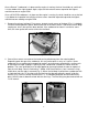
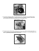
3. After removing the lock screw, the fuel valve & seat assembly may be rotated counter-clockwise
with a 5/8-inch wrench. Once the threads are no longer engaged with the bowl threads, the entire
assembly can be extracted (Fig. 4). O-rings may provide some resistance which can be easily
overcome by pulling straight upward.
Figure 4
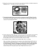
4. The plastic baffle installed in the fuel bowl should be removed and reinstalled when the carburetor
is assembled. This baffle is essential to proper float operation and should not be left out. Dual feed
bowls utilize the inlet cavity as a baffle, so a separate piece is not required.
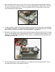
5. Removal of four Phillips screws allows the accelerator pump housing to be lifted from the fuel bowl
(Fig. 5). The pump diaphragm is located below this cover. This should now be discarded as a new
diaphragm is included with your package. A return spring is located beneath the diaphragm and it
should be saved for reuse.
Figure 5
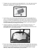
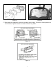
6. The metering block must also be stripped of its removable parts prior to being cleaned. The jets
should be removed with a wide-blade screwdriver.