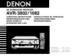
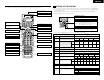
AV SURROUND RECEIVER AVR-3802/1082 OPERATING INSTRUCTIONS BEDIENUNGSANLEITUNG MODE D’EMPLOI ISTRUZIONI PER L’USO INSTRUCCIONES DE OPERACION GEBRUIKSAANWIJZING BRUKSANVISNING POWER ON / SOURCE OFF RC-884 REMOTE CONTROL UNIT TV CD VCR DBS/CABLE CDR/MD/ TAPE RECEIVER VDP DVD DISPLAY MENU SURR. PARA.
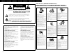
ENGLISH DEUTSCH FRANCAIS ITALIANO ESPAÑOL NEDERLANDS CAUTION SVENSKA NOTE ON USE / HINWEISE ZUM GEBRAUCH / OBSERVATIONS RELATIVES A L’UTILISATION / NOTE SULL’USO NOTAS SOBRE EL USO / ALVORENS TE GEBRUIKEN / OBSERVERA RISK OF ELECTRIC SHOCK DO NOT OPEN CAUTION: TO REDUCE THE RISK OF ELECTRIC SHOCK, DO NOT REMOVE COVER (OR BACK). NO USER SERVICEABLE PARTS INSIDE. REFER SERVICING TO QUALIFIED SERVICE PERSONNEL.
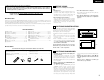
ENGLISH We greatly appreciate your purchase of the AVR-3802. To be sure you take maximum advantage of all the features the AVR-3802 has to offer, read these instructions carefully and use the set properly. Be sure to keep this manual for future reference, should any questions or problems arise. 2 2 “SERIAL NO. PLEASE RECORD UNIT SERIAL NUMBER ATTACHED TO THE REAR OF THE CABINET FOR FUTURE REFERENCE” 2 INTRODUCTION Thank you for choosing the DENON AVR-3802 Digital Surround A / V receiver.
ENGLISH 4 FEATURES 1. Digital Surround Sound Decoding Featuring 32 bit high speed DSP, operating entirely in digital domain, surround sound from digital sources such as DVD, LD, DTV and satellite are faithfully re-created. 2. Dolby Pro Logic II decoder Dolby Pro Logic II is a new format for playing multichannel audio signals that offers improvements over conventional Dolby Pro Logic.
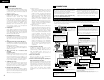
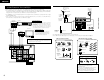
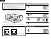
ENGLISH Connecting video components Connecting a video component equipped with S-Video jacks • To connect the video signal, connect using a 75 Ω/ohms video signal cable cord. Using an improper cable can result in a drop in video quality. • When making connections, also refer to the operating instructions of the other components.
ENGLISH Connecting a Video Component Equipped with Color Difference (Component - Y, PR/CR, PB/CB) Video Jacks (DVD Player) Connecting the antenna terminals DIRECTION OF BROADCASTING STATION • When making connections, also refer to the operating instructions of the other components. • The signals input to the color difference (component) video jacks are not output from the VIDEO output jack (yellow) or the S-Video output jack.
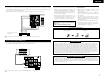
ENGLISH Connecting the external input (EXT. IN) jacks Speaker system connections • These jacks are for inputting multi-channel audio signals from an outboard decoder, or a component with a different type of multi-channel decoder, such as a DVD Audio player, or a multi-channel SACD player, or other future multi-channel sound format decoder. • When making connections, also refer to the operating instructions of the other components.
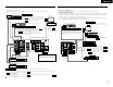
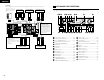
ENGLISH Connections • When making connections, also refer to the operating instructions of the other components. Connection jack for subwoofer with built-in amplifier (super woofer), etc. FRONT SPEAKER SYSTEMS (L) CENTER SPEAKER SYSTEM (R) SURROUND SPEAKER SYSTEMS (A) (L) 6 PART NAMES AND FUNCTIONS Front Panel • For details on the functions of these parts, refer to the pages given in parentheses ( ).
ENGLISH 7 SETTING UP THE SYSTEM Remote control unit • For details on the functions of these parts, refer to the pages given in parentheses ( ). Remote control signal transmitter ...................................(16) • Once all connections with other AV components have been completed as described in “CONNECTIONS” (see pages 4 to 8), make the various settings described below on the monitor screen using the AVR-3802’s on-screen display function.
ENGLISH NOTES: • The on-screen display signals are not output from the color difference (component) video signal (MONITOR OUT) jacks. • The on-screen display signals are output with priority to the S-VIDEO MONITOR OUT jack during playback of a video component. For example, if the TV monitor is connected to both the AVR-3802’s S-Video and video monitor output jacks and signals are input to the AVR-3802 from a video source (VDP, etc.
ENGLISH 2 Selecting the surround speakers for the different surround modes Switch to the speaker configuration screen. ENTER This screen is displayed when using both surround speakers A and B. • At this screen preset the surround speakers to be used in the different surround modes. SHIFT 3 TUNING BAND MODE TUNING Set whether or not speakers are connected and, if so, their size parameters.
ENGLISH NOTES: — Assignment of low frequency signal range — • The only signals produced from the subwoofer channel are LFE signals (during playback of Dolby Digital or DTS signals) and the low frequency signal range of channels set to “Small” in the setup menu. The low frequency signal range of channels set to “Large” are produced from those channels.
ENGLISH 4 Setting the channel level Once “Meter” or “Feet” is selected in Step 3, the Delay Time screen appears automatically. 5 • • • • 1 Select the speaker to be set. TUNING Use this setting to adjust so that the playback level between the different channels is equal. From the listening position, listen to the test tones produced from the speakers to adjust the level. The level can also be adjusted directly from the remote control unit. (For details, see page 27.
ENGLISH 7 Select “Yes”. When you adjust the channel levels while in the SYSTEM SETUP CHANNEL LEVEL mode, the channel level adjustments made will affect ALL surround modes. Consider this mode a Master Channel Level adjustment mode. After you have completed the SYSTEM SETUP CHANNEL LEVEL adjustments, you can then activate the individual surround modes and adjust channel levels that will be remembered for each of those modes.
ENGLISH Setting the multi vol. level Set the multi pre-out output level adjustment. 1 TUNING ENTER BAND MODE SHIFT At the “System Setup Menu” screen, select “Multi Vol. Level” and press the ENTER button. Auto tuner preset Use this to automatically search for FM broadcasts and store up to 40 stations at preset channels A1 to 8, B1 to 8, C1 to 8, D1 to 8 and E1 to 8.
ENGLISH 8 REMOTE CONTROL UNIT After completing system setup This button can be pressed at any time during the system setup process to complete the process. 1 At the System Setup Menu, press the SYSTEM SETUP button. SETUP • The included remote control unit (RC-884) can be used to operate not only the AVR-3802 but other remote control compatible DENON components as well.
ENGLISH Operating DENON audio components 1 Preset memory Use the mode selector buttons to select the component you want to operate. The mode switches between “AMP”, “TUNER” and “MULTI” each time the RECEIVER button is pressed, between “CDR”, “MD” and “TAPE” each time the CDR/MD/TAPE button is pressed, between “DBS” and “CABLE” each time the DBS/CABLE button is pressed, and between “DVD” and “DVD SETUP” each time the DVD button is pressed, and between “VCR” and “VCR2” eachtime the VCR button is pressed.
ENGLISH The preset codes are as follows upon shipment from the factory and after resetting: TV, VCR......................................................................HITACHI CD, MD, TAPE, CDR, VDP, DVD, DVD SETUP .........DENON DBS ...........................................................................GENERAL INSTRUMENT CABLE .......................................................................JERROLD 2 Some models cannot be operated with this remote control unit. 1.
ENGLISH Learning function System call If your AV component is not a Denon product or if it cannot be operated using the preset memory, it can be controlled with the included remote control unit by storing its remote control signals in the remote control unit. 1 Press the power ON/SOURCE button and the OFF button simultaneously. • “SET UP” appears on the remote control unit’s display. POWER 1, 5, 8 ON / SOURCE OFF CD CDR/MD/ TAPE RECEIVER ON / SOURCE VCR DBS/CABLE VDP DVD DISPLAY MENU SURR.
ENGLISH 5 Use the D and H cursor buttons to select the mode for the button at which the system call signals are to be registered, then press the ENTER button. 7 q Press the mode selector button according to the button with the remote control signals to be registered. TUNING TV CD VCR DBS/CABLE 4 CDR/MD/ TAPE RECEIVER VDP q To reset CALL 1 or CALL 2, select “SYS CALL 1” or SYS CALL 2”, then press the ENTER button.
ENGLISH 4 Use the D and H cursor buttons to display “RESET PRE” on the remote control unit, then press the ENTER button. • After “SEL PRE” is displayed on the remote control unit’s display, the registered preset memory is displayed on the remote control unit’s display. 6 When the mode you want to reset is shown on the remote control unit’s display, press the ENTER button to reset the preset memory. (4) All reset function • This function is for resetting all the settings to the factory defaults.
ENGLISH 9 OPERATION Auto search function • The set is equipped with a function for searching for the registration number if you do not know the preset code (a 4-digit number) when setting the preset memory. 1 2 For TV, DBS or CABLE components, turn on the component’s power. For CD, MD, TAPE, DVD, VCR and VDP component’s, turn on the component’s power and load a disc or tape. Press the power ON/SOURCE button and the OFF button simultaneously. • “SET UP” appears on the remote control unit’s display.
ENGLISH • Selecting the PCM mode Press the PCM button to switch to the PCM signal input. Playing the input source 1 1 5 BAND 2 3 PCM VOLUME AUTO ENTER SHIFT SKIP MUTING - PHONO CD 1 2 3 CDR/ TAPE VDP DVD 4 5 6 VCR-1 VCR-2 /V.AUX TV/DBS 7 8 9 TV/ VCR 0 +10 PTY SPEAKER DIGITAL ANALOG • In the DIGITAL PCM mode 4 - TEST TONE INPUT AUTO 1 • Selecting the DTS mode Press the DTS button to switch to the DTS signal input. RT DTS OUTPUT DOLBY/DTS SURROUND DSP SIMU.
ENGLISH Playback using the external input (EXT. IN) jacks 1 Set the external input (EXT. IN) mode. Press the EXT. IN to switch the external input. After starting playback [1] Adjusting the sound quality (TONE) The tone control function will not work in the Direct mode. B 1 EXT.IN EXT.IN The tone switches as follows each time the TONE CONTROL button is pressed.
ENGLISH [4] Combining the currently playing sound with the desired image 1 Simulcast playback Use this switch to monitor a video source other than the audio source. VIDEO SELECT Press the VIDEO SELECT button repeatedly until the desired source appears on the display. Multi-source recording/playback [1] Playing one source while recording another (REC OUT mode) B 1 Press the REC/MULTI button. REC / MULTI 2,4 2 B (Main unit) (Main unit) 1 Cancelling simulcast playback.
ENGLISH [3] Remote control unit operations during multi-source playback (selecting the input source) This operation is possible when Multi mode is selected. This operation is not possible in the REC OUT mode. 1 Select “MULTI” using the RECEIVER button. TV CD VCR DBS/CABLE CDR/MD/ TAPE RECEIVER 1 RECEIVER VDP DVD MENU DISPLAY SURR. PARA. OSD SETUP RETURN TUNING A/B (Remote Control unit) MEMORY BAND MODE CHANNEL 2 Press the input source button. The multi source switches directly.
ENGLISH 10 SURROUND Fader function • This function makes it possible to lower the volume of the front channels (FL, C and FR) or the rear channels (SL, SR, SBL and SBR) together. Use it for example to adjust the balance of the sound from the different positions when playing multi-channel music sources. Before playing with the surround function • Before playing with the surround function, be sure to use the test tones to adjust the playback level from the different speakers.
ENGLISH 3 Set the surround parameter mode. Display SURROUND PARAMETER SURR. PARA. (Main unit) MODE CINEMA (Remote control unit) The on-screen display differs according to whether the operation is performed from the main unit or the remote control unit. 4 Select the play mode. TUNING SELECT BAND MODE TUNING (Main unit) (Remote control unit) Surround parameters q Pro Logic II Mode: The Cinema mode is for use with stereo television shows and all programs encoded in Dolby Surround.
ENGLISH 3 Play a program source with the , mark. Light • The Dolby Digital indicator lights when playing Dolby Digital sources. Light • The DTS indicator lights when playing DTS sources. DIGITAL Operate the 6.1/7.1 Surround button to switch Surround Back CH ON/OFF. 6.1 / 7.1 SURROUND • The SIGNAL DETECT indictor lights SIGNAL DETECT Light when playing DTS-ES/6.1-channel surround sources containing the identification signal.
ENGLISH 11 DSP SURROUND SIMULATION • The AVR-3802 is equipped with a high performance DSP (Digital Signal Processor) which uses digital signal processing to synthetically recreate the sound field. One of seven preset surround modes can be selected according to the program source and the parameters can be adjusted according to the conditions in the listening room to achieve a more realistic, powerful sound.
ENGLISH • Operating the surround mode and surround parameters from the main unit‘s panel. 1 Turn the SELECT knob to select the surround mode. Tone control setting • Use the tone control setting to adjust the bass and treble as desired. • To operate the tone control from the remote control unit. B SELECT 1 SURR. PARA.
ENGLISH Surround parameters e MODE: (DTS NEO:6) • Cinema This mode is optimum for playing movies. Decoding is performed with emphasis on separation performance to achieve the same atmosphere with 2-channel sources as with 6.1-channel sources. This mode is effective for playing sources recorded in conventional surround formats as well, because the in-phase component is assigned mainly to the center channel (C) and the reversed phase component to the surround (SL, SR and SB channels).
ENGLISH 12 LISTENING TO THE RADIO 5 BAND Auto tuning 1 TUNING MODE TUNING 1 Set the input function to “TUNER”. (Remote control unit) Press the TUNING UP or DOWN button to tune in the desired station. The frequency changes when the continuously button is held in. B FUNCTION TUNER 1 (Main unit) 2 Preset memory (Remote control unit) Press the RECEIVER button on the remote control unit to select “TUNER”.
ENGLISH 2 Traffic Program (TP) TP identifies programs that carry traffic announcements. This allows you to easily find out the latest traffic conditions in your area before you leaving home. 2 Radio Text (RT) RT allows the RDS station to send text messages that appear on the display. NOTE: The operations described below using the RDS, PTY and RT buttons will not function in areas in which there are no RDS broadcasts. Recalling preset stations • To call out preset stations from the remote control unit.
ENGLISH PTY search TP search Use this function to find RDS stations broadcasting a designated program type (PTY). For a description of each program type, refer to “Program Type (PTY)”. 1 TUNER 1 Use this function to find RDS stations broadcasting traffic program (TP stations). 1 Set the input function to “TUNER”. TUNER 1 Set the input function to “TUNER”.
ENGLISH 13 LAST FUNCTION MEMORY 15 TROUBLESHOOTING • This unit is equipped with a last function memory which stores the input and output setting conditions as they were immediately before the power is switched off. This function eliminates the need to perform complicated resettings when the power is switched on. • The unit is also equipped with a back-up memory. This function provides approximately one week of memory storage when the main unit’s power switch is off and with the power cord disconnected.
ENGLISH Remote control unit Symptom Cause Measures • Batteries dead. • Remote control unit too far from this unit. This unit does not operate • Obstacle between this unit and properly when remote control remote control unit. unit is used. • Different button is being pressed. • < and > ends of battery inserted in reverse. Page • Replace with new batteries. • Move closer. 16 16 • Remove obstacle. 16 • Press the proper button. • Insert batteries properly.
ENGLISH (3) When using different surround speakers for movies and music To achieve more effective surround sound for both movies and music, use different sets of surround speakers and different surround modes for the two types of sources. Speaker setting examples Here we describe a number of speaker settings for different purposes. Use these examples as guides to set up your system according to the type of speakers used and the main usage purpose. Front speakers Center speaker 1.
ENGLISH Surround The AVR-3802 is equipped with a digital signal processing circuit that lets you play program sources in the surround mode to achieve the same sense of presence as in a movie theater. Dolby Surround (1) Dolby Digital (Dolby Surround AC-3) Dolby Digital is the multi-channel digital signal format developed by Dolby Laboratories. Dolby Digital consists of up to “5.
ENGLISH DTS-ES Extended Surround TM DTS Digital Surround Digital Theater Surround (also called simply DTS) is a multi-channel digital signal format developed by Digital Theater Systems. DTS offers the same “5.1” playback channels as Dolby Digital (front left, front right and center, surround left and surround right) as well as the stereo 2-channel mode.
ENGLISH System setup items and default values (set upon shipment from the factory) System setup Surround modes and parameters Default settings Front L/R CENTER SURROUND L/R SUBWOOFER SURROUND BACK L/R When playing Dolby Digital Signals DIRECT C E E B E C C C C STEREO C E E B E C C C C EXTERNAL INPUT C B B B B E E E C C B B B B * C E C C DTS NEO:6 C B B B B E E C C DOLBY DIGITAL C B B B B C E E E C B B B B E C E E Channel output (
ENGLISH 17 SPECIFICATIONS 2 Audio section • Power amplifier Rated output: Dynamic power: Output terminals: • Analog Input sensitivity / input impedance: Frequency response: S/N: Distortion: Rated output: • Digital D/A output: 105 W + 105 W (8 Ω/ohms, 20 Hz ~ 20 kHz with 0.05% T.H.D.) 150 W + 150 W (6 Ω/ohms, 1 kHz with 0.7% T.H.D.) Center: 105 W (8 Ω/ohms, 20 Hz ~ 20 kHz with 0.05% T.H.D.) 150 W (6 Ω/ohms, 1 kHz with 0.7% T.H.D.) Surround: 105 W + 105 W (8 Ω/ohms, 20 Hz ~ 20 kHz with 0.05% T.H.D.