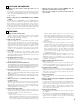
AV SURROUND RECEIVER AVR-3803/1083 OPERATING INSTRUCTIONS AMP REMOTE SENSOR SURROUND BACK CH SIGNAL AUTO INPUT PCM VOLUME LEVEL OUTPUT DIGITAL ON / STANDBY DTS SIGNAL DETECT 2 We greatly appreciate your purchase of the AVR-3803/1083. 2 To be sure you take maximum advantage of all the features the AVR-3803/1083 has to offer, read these instructions carefully and use the set properly. Be sure to keep this manual for future reference, should any questions or problems arise. “SERIAL NO.
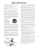
SAFETY PRECAUTIONS CAUTION WARNING: TO PREVENT FIRE OR SHOCK HAZARD, DO NOT EXPOSE THIS APPLIANCE TO RAIN OR MOISTURE. TO PREVENT ELECTRIC SHOCK, MATCH WIDE BLADE OF PLUG TO WIDE SLOT, FULLY INSERT. ATTENTION CAUTION POUR ÉVITER LES CHOCS ÉLECTRIQUES, INTERODUIRE LA LAME LA PLUS LARGE DE LA FICHE DANS LA BORNE CORRESPONDANTE DE LA PRISE ET POUSSER JUSQU’ AU FOND. RISK OF ELECTRIC SHOCK DO NOT OPEN CAUTION: TO REDUCE THE RISK OF ELECTRIC SHOCK, DO NOT REMOVE COVER (OR BACK).
SAFETY INSTRUCTIONS 1. 2. 3. 4. 5. 6. 7. 8. 9. 10. 11. 12. Read Instructions – All the safety and operating instructions should be read before the product is operated. Retain Instructions – The safety and operating instructions should be retained for future reference. Heed Warnings – All warnings on the product and in the operating instructions should be adhered to. Follow Instructions – All operating and use instructions should be followed.
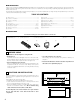
2 INTRODUCTION Thank you for choosing the DENON AVR-3803/1083 Digital A / V Surround Receiver. This remarkable component has been engineered to provide superb surround sound listening with home theater sources such as DVD, as well as providing outstanding high fidelity reproduction of your favorite music sources. As this product is provided with an immense array of features, we recommend that before you begin hookup and operation that you review the contents of this manual before proceeding.
3 CAUTIONS ON HANDLING • Switching the input function when input jacks are not connected A clicking noise may be produced if the input function is switched when nothing is connected to the input jacks. If this happens, either turn down the MASTER VOLUME control or connect components to the input jacks. • Whenever the power switch is in the STANDBY state, the apparatus is still connected on AC line voltage. Please be sure to unplug the cord when you leave home for, say, a vacation.
5 CONNECTIONS • Do not plug in the AC cord until all connections have been completed. • Be sure to connect the left and right channels properly (left with left, right with right). • Insert the plugs securely. Incomplete connections will result in the generation of noise. • Use the AC OUTLETS for audio equipment only. Do not use them for hair driers, etc. • Note that binding pin plug cords together with AC cords or placing them near a power transformer will result in generating hum or other noise.
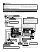
Connecting the video components • • • • • To connect the video signal, connect using a 75 Ω/ohms video signal cable cord. Using an improper cable can result in a drop in video quality. When making connections, also refer to the operating instructions of the other components. The AVR-3803/1083 is equipped with a function for up-converting video signals. The signal connected to the video signal terminal is output to the S-Video and component video monitor out terminals.
Connecting the video components equipped with S-Video jacks • When making connections, also refer to the operating instructions of the other components. • A note on the S input jacks The input selectors for the S inputs and Video inputs work in conjunction with each other. • The AVR-3803/1083 is equipped with a function for converting video signals. • The signal connected to the S-Video signal terminal is output to the composite video and component video monitor out terminals.
Connecting the video component equipped with Color Difference (Component - Y, PR/CR, PB/CB) Video jacks • When making connections, also refer to the operating instructions of the other components. • The signals input to the color difference (component) video jacks are not output to the VIDEO output jack (yellow) or the S-Video output jack. • Some video sources with component video outputs are labeled Y, CB, CR, or Y, Pb, Pr, or Y, R-Y, B-Y. These terms all refer to component video color difference output.
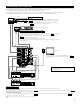
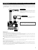
Connecting the antenna terminals DIRECTION OF BROADCASTING STATION AM LOOP ANTENNA (Supplied) FM ANTENNA 75 Ω/ohms COAXIAL CABLE AM OUTDOOR ANTENNA FM INDOOR ANTENNA (Supplied) GROUND • An F-type FM antenna cable plug can be connected directly. AM loop antenna assembly 1 4 2 Remove the vinyl tie and take out the connection line. Connect to the AM antenna terminals. 2. Insert the conductor. 3. Return the lever. 3 Bend in the reverse direction. a. With the antenna on top any stable surface.
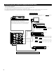
Connecting the external input (EXT. IN) jacks • These jacks are for inputting multi-channel audio signals from an outboard decoder, or a component with a different type of multi-channel decoder, such as a DVD Audio player, a multi-channel SACD player, or other future multi-channel sound format decoder. • When making connections, also refer to the operating instructions of the other components.
Speaker system connections • Connect the speaker terminals with the speakers making sure that like polarities are matched (≈ with ≈ , √ with √ ). Mismatching of polarities will result in weak central sound, unclear orientation of the various instruments, and the sense of direction of the stereo being impaired. • When making connections, take care that none of the individual conductors of the speaker cord come in contact with adjacent terminals, with other speaker cord conductors, or with the rear panel.
Protector circuit • This unit is equipped with a high-speed protection circuit. The purpose of this circuit is to protect the speakers under circumstances such as when the output of the power amplifier is inadvertently short-circuited and a large current flows, when the temperature surrounding the unit becomes unusually high, or when the unit is used at high output over a long period which results in an extreme temperature rise.
6 PART NAMES AND FUNCTIONS Front Panel • For details on the functions of these parts, refer to the pages given in parentheses ( ). @8 @7 @6 @5 @4 @3 @2 REMOTE SENSOR @1 @0 ON / STANDBY q AUTO w er t y OUTPUT DTS SIGNAL DETECT u i o !0 !1 !2 q Power ON/STANDBY switch..............................................(47, 70) w Headphones jack (PHONES) ....................................................(51) e VIDEO SELECT button .............................................................
Remote control unit • For details on the functions of these parts, refer to the pages given in parentheses ( ). Remote control signal transmitter ..............................................(34) Power buttons .................................(36~47) ZONE 2 buttons .....................................(53) ZONE1 (MAIN) buttons ..........................(53) Mode selector buttons .................................(35, 37, 47, 53) Tuner system/System buttons.....................
7 SETTING UP THE SYSTEM • Once all connections with other AV components have been completed as described in “CONNECTIONS” (see pages 6 to 13), make the various settings described below on the monitor screen using the AVR-3803/1083’s on-screen display function. These settings are required to set up the listening room’s AV system centered around the AVR-3803/1083. • Use the following buttons to set up the system: • Check that the remote control unit is set to AMP mode.
System setup !2 !3 !4 Trigger Out Setup Auto Tuner Presets Setup Lock Default settings TUNER CDR/TAPE PHONO CD OFF OFF DVD VDP TV DBS VCR-1 ON ON ON ON ON VCR-2 V. AUX Set the Trigger Out output for the different input sources. FM stations are received automatically and stored in the memory. OFF OFF A1 ~ A8 87.5/89.1/98.1/107.9/90.1/90.1/90.1/90.1 MHz B1 ~ B8 520/600/1000/1400/1500/1710 kHz, 90.1/90.1 MHz C1 ~ C8 90.1 MHz D1 ~ D8 90.1 MHz E1 ~ E8 90.
Before setting up the system 1 2 Check that all the connections are correct, then turn on the main unit’s power. Display the System Setup Menu. Setting the type of speakers • The composition of the signals output to the different channels and the frequency response are adjusted automatically according to the combination of speakers actually being used. 1 At the System Setup Menu select “Speaker Configuration”. 2 Switch to the speaker configuration screen.
• Parameters Large...................Select this when using speakers that have sufficient performance for reproducing bass sound below the frequency set for the Crossover Frequency mode. Small...................Select this when using speakers that do not have sufficient performance for reproducing bass sound below the frequency set for the Crossover Frequency mode. When this is set, bass sound with a frequency below the frequency set for the Crossover Frequency mode is sent to the subwoofer.
2 Select the “Subwoofer Mode”. Select the setting. 3 Enter the setting. The System Setup Menu reappears. NOTES: — Assignment of low frequency signal range — • The only signals produced from the subwoofer channel are LFE signals (during playback of Dolby Digital or DTS signals) and the low frequency signal range of channels set to “SMALL” in the setup menu. The low frequency signal range of channels set to “LARGE” are produced from those channels.
Setting the Delay Time • Input the distance between the listening position and the different speakers to set the delay time for the surround mode. • The delay time can be set separately for surround speakers A and B. Preparations: Measure the distances between the listening position and the speakers (L1 to L5 on the diagram at the right).
6 Set the distance between the center speaker and listening position. The distance changes in units of 1 foot (0.1 meters) each time the button is pressed. Select the value closest to the measured distance. Example: When the distance is set to 12 feet for the center speaker If “Yes” is selected for “Default”, the settings are automatically reset to the default values. Please note that the difference of distance for every speaker should be 20 ft (6.0 m) or less.
4 Select the mode. Select “Auto” or “Manual”. • Auto: Adjust the level while listening to the test tones produced automatically from the different speakers. • Manual: Select the speaker from which you want to produce the test tone to adjust the level. Example: When the “Auto” mode is selected Select “Surr. Sp.”, then select the surround speaker(s) from which you want to produce the test tone (A, B or A+B). • Surr. Sp.
9 After the above settings are completed, press the ENTER button. The “Channel Level” screen reappears. To cancel the settings, select “Level Clear” and “Yes” on the “Channel Level” screen, then make the settings again. The level of each channel should be adjusted to 75 dB (C-weighted, slow meter mode) on a sound level meter at the listening position. If a sound level meter is not available adjust the channels by ear so the sound levels are the same.
NOTES: • The OPTICAL 4 and 5 jacks on the AVR-3803/1083’s rear panel are equipped with an optical digital output jack for recording digital signals on a CD recorder, MD recorder or other digital recorder. Use this for digital recording between a digital audio source (stereo - 2 channel) and a digital audio recorder. • Do not connect the output of the component connected to the OPTICAL 4 OUT jack on the AVR-3803/1083’s rear panel to any jack other than the OPTICAL 4 IN jack.
[2] Setting the Video Input Mode 1 At the System Setup Menu select “Video Setup” and press the ENTER button. 2 The “Video Setup” screen appears. Select “Video Input Mode” and press the ENTER button. 3 Switch the Video Input Mode screen. 4 q Select the input source for which you want to set the Video Input Mode. w Select the mode.
Setting the Dolby Digital Setup Sets the down-mixing method when not using a center speaker or surround speakers. OFF: The dynamic range is not compressed. ON: The dynamic range is compressed automatically according to the combination of speakers being used. 1 At the System Setup Menu select “Dolby Digital Setup” and press the ENTER button. 2 Select “ON” if you want to use the Dolby Digital Down-mix, “OFF” if you do not want to use it. 3 Enter the setting. The System Setup Menu reappears.
4 Enter the setting. At the “Zone2 Control” screen, select “Exit” and press the ENTER button. The System Setup Menu reappears. [2] Setting the Zone2 vol. level Set the Zone 2 pre-out output level adjustment. 1 At the System Setup Menu select “Zone2 Control” and press the ENTER button. 2 The “Zone2 Control” screen appears. Select “Zone2 Vol. Level” and press the ENTER button. 3 Select the desired settimg. Variable: The level can be adjusted freely using the buttons on the remote control unit.
Setting the Ext. In Subwoofer Level • Set the method of playback of the analog input signal connected to the Ext.In Subwoofer. 1 At the System Setup Menu select “Ext.In Subwoofer Level”. 2 Switch to the Ext.In Subwoofer Level screen. 3 Select the desired setting. 4 Enter the setting. The System Setup Menu reappears. Select according to the specifications of the player being used. Also refer to the player’s operating instructions. +15dB (default) recommended. (0, +5, 10 and +15 can be selected.
2 Select “ON” if you want to use the auto surround mode, “OFF” if you do not want to use it. 3 Enter the setting. The System Setup Menu reappears. Setting the On Screen Display (OSD) • Use this to turn the on-screen display (messages other than the menu screens) on or off. • Sets the on-screen display’s display mode. Mode 1: Prevents flickering of the on-screen display when there is no video signal. Mode 2: Flickering is not prevented.
Setting the Trigger Out Setup • Sets the Trigger Out output for the different input sources. 1 At the System Setup Menu select “Trigger Out Setup”. 2 Switch to the Trigger Out Setup screen. 3 4 Select the input source and select “ON” or “OFF”. Enter the setting. The System Setup Menu reappears. Auto Tuner Presets Use this to automatically search for FM broadcasts and store up to 40 stations at preset channels A1 to 8, B1 to 8, C1 to 8, D1 to 8 and E1 to 8.
3 Use the CURSOR button to select “Yes”. “Search” flashes on the screen and searching begins. “Completed” appears once searching is completed. The display automatically switches to screen. This completes system setup. Once these settings are made, there is no need to change them unless different AV components are connected or the speakers are repositioned. Protecting the setting The system setup settings can be locked so that they cannot be changed easily.
After completing system setup This button can be pressed at any time during the system setup process to complete the process. 1 At the System Setup Menu, press the SYSTEM SETUP button. The changed settings are entered and the on-screen display turns off.
8 REMOTE CONTROL UNIT • The included remote control unit (RC-921) can be used to operate not only the AVR-3803/1083 but other remote control compatible DENON components as well. In addition, the memory contains the control signals for other remote control units, so it can be used to operate non-Denon remote control compatible products. Inserting the batteries q Remove the remote control unit’s rear cover. w Set three R6P/AA batteries in the battery compartment in the indicated direction.
Operating DENON audio components 1 Use the mode selector buttons to select the component you want to operate. The function switches as shown below each time one of the mode buttons is pressed. AMP/ZONE2 : AMP, ZONE2 CDR/MD : CDR,MD DBS/CABLE : DBS, CABLE VCR-1/VCR-2 : VCR-1, VCR-2 DVD/VDP : DVD, VDP 2 AMP 1 Operate the audio component. • For details, refer to the component’s operating instructions. It may not be possible to operate some models. 1.
Preset memory The included remote control unit can be used to operate devices of different brands by registering the preset number corresponding to the brand of your device. For some models the remote control unit or the device may not operate properly. In this case, use the learning function (page 39) to store your device’s remote control signals in the included remote control unit. For instructions on resetting the preset memory, see page 42.
Operating a component stored in the preset memory 1 Press the mode selector button for the component you want to operate. AMP 1 NOTE: • For the DVD player remote control buttons, function names may differ according to manufacturer. Compare with the remote control operation of the various components. 2 Operate the component. • For details, refer to the component’s operating instructions. Some models cannot be operated with this remote control unit. 2. Video disc player (VDP) system buttons 1.
3. Video deck (VCR-1/VCR-2) system buttons POWER : Power on/standby (ON/SOURCE) 6,7 : Manual search (forward and reverse) 2 : Stop 1 : Play 3 : Pause Channel +, – : Channels VCR1 4.
Learning function If your AV component is not a Denon product or if it cannot be operated using the preset memory, it can be controlled with the accessorious remote control unit by storing its remote control signals in the remote control unit. For some remote control signals it is not possible to “learn” the signals or the device will not operate properly. In such cases use the remote control unit included with the device to operate it. 1 Press the power ON/SOURCE button and the OFF button simultaneously.
System call The accessorious remote control unit is equipped with “system call” function allowing a series of remote control signals to be transmitted by pressing a single button. This function can be used for example to turn on the amplifier’s power, select the input source, turn on the monitor TV’s power, turn on the source component’s power and set the source to the play mode, all at a signal button. (1) System call buttons Up to 10 signals each can be stored at the “CALL1” and “CALL2” buttons.
NOTES: • The remote control signals of the buttons pressed while registering the system call signals are emitted, so be careful not to operate the components accidentally (cover the remote sensors, for example). • If you exceed the number of signals that can be registered, “FULL” appears on the remote control unit’s display and only the number of signals that can be registered are registered (up to 10 operations).
Setting the back light’s lighting time 1 Press the power ON/SOURCE button and the OFF button at the same time. • “PRE” appears on the remote control unit’s display. 2 Use the • and ª cursor buttons to display “BKLT” on the remote control unit, then press the ENTER button. • “05SEC” appears on the remote control unit’s display. 1 DVD 1 2, 3 3 Use the • and ª cursor buttons to adjust the lighting time (3 sec ~ 30 sec), then press the ENTER button. • “OK” is displayed and that lighting time is set.
3 Use the • and ª cursor buttons to display “PRE” on the remote control unit, then press the ENTER button. • After “SEL” is displayed on the remote control unit’s display, the registered preset memory is displayed on the remote control unit’s display. 4 Use the • and ª cursor buttons to select the code to be reset. 5 When the mode you want to reset is shown on the remote control unit’s display, press the ENTER button to reset the preset memory.
(3) Resetting the system call buttons 1 Press the power ON/SOURCE button and the OFF button at the same time. • “PRE” appears on the remote control unit’s display. 2 Use the • and ª cursor buttons to display “RST” on the remote control unit, then press the ENTER button. • “PRE” appears on the remote control unit’s display. 3 Use the • and ª cursor buttons to display “CALL” on the remote control unit, then press the ENTER button. • “SEL” appears on the remote control unit’s display.
(4) Resetting the punch through setting 1 Press the power ON/SOURCE button and the OFF button at the same time. • “PRE” appears on the remote control unit’s display. 2 Use the • and ª cursor buttons to display “RST” on the remote control unit, then press the ENTER button. 3 Use the • and ª cursor buttons to display “PUNCH” on the remote control unit, then press the ENTER button. • “SEL” appears on the remote control unit’s display.
(5) All reset function • This function is for resetting all the settings to the factory defaults. 1 Press the power ON/SOURCE button and the OFF button at the same time. “PRE” appears on the remote control unit’s display. 2 Use the • and ª cursor buttons to display “RST” on the remote control unit, then press the ENTER button. 1 DVD 1 2, 3 3 46 Use the • and ª cursor buttons to display “ALL” on the remote control unit, then press the ENTER button.
9 OPERATION Before operating 1 2 Refer to “CONNECTIONS” (pages 6 to 13) and check that all connections are correct. Select “AMP” using the AMP button. (only when operating with the remote control unit) 3 (Remote control unit) 3 Turn on the power. Press the POWER switch (button). AMP 3 ON/STANDBY Light (Main unit) 2 (Remote control unit) When pressed, the power turns on and the display lights. The sound is muted for several seconds, after which the unit operates normally.
Playing the input source 1 1 5 1 3 2 3 5 1 Select the input source to be played. Example: CD FUNCTION (Main unit) (Remote control unit) To select the input source when ZONE2/REC OUT or TUNING PRESET is selected, press the SOURCE button then operate the input function selector. 2 (Main unit) Select the input mode. • Selecting the analog mode Press the ANALOG button to switch to the analog input. (Main unit) (Remote control unit) • Selecting the external input (EXT. IN) mode Press the EXT.
3 Input mode display Select the play mode. One of these lights, depending on the input signal. • In the AUTO mode Example: Stereo INPUT SELECT AUTO PCM DTS DIGITAL ANALOG • In the DIGITAL PCM mode INPUT AUTO (Main unit) PCM DTS DIGITAL (Remote control unit) To select the surround mode while adjusting the surround parameters, channel volume or tone control, press the surround mode button then operate the selector.
Playback using the external input (EXT. IN) jacks 1 Set the external input (EXT. IN) mode. Press the EXT. IN to switch the external input. (Main unit) (Remote control unit) Once this is selected, the input signals connected to the FL (front left), FR (front right), C (center), SL (surround left), SR (surround right), SBL (surround back left) and SBR (surround back right) channels of the EXT.
After starting playback [1] Adjusting the sound quality (TONE) The tone control function will not work in the direct mode. 1 The tone switches as follows each time the TONE CONTROL button is pressed. BASS TREBLE (Main unit) 2 With the name of the volume to be adjusted selected, turn the SELECT knob to adjust the level. 2 31 SELECT (Main unit) • To increase the bass or treble: Turn the control clockwise. (The bass or treble sound can be increased to up to +10 dB in steps of 2 dB.
[5] Checking the currently playing program source, etc. 1 On screen display • Each time an operation is performed, a description of that operation appears on the display connected to the unit’s VIDEO MONITOR OUT jack. Also, the unit’s operating status can be checked during playback by pressing the remote control unit’s ON SCREEN/DISPLAY button. Such information as the position of the input selector and the surround parameter settings is output in sequence.
[2] Outputting a program source to an amplifier, etc., in a different room (ZONE2 mode) 1 Press the ZONE2 button. 3,5 3 Light (Main unit) 2 Press the ZONE2/REC button. The display switches as follows each time the button is pressed. 2 With “ZONE2 SOURCE” displayed, turn the FUNCTION knob and select the source you wish to output. • The indicator of the selected source light.
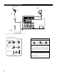
Multi-zone playback with multi-source MULTI ZONE MUSIC ENTERTAINMENT SYSTEM • When the outputs of the “ZONE 2” OUT terminals are wired and connected to integrated amplifiers installed in other rooms, different sources can be played in rooms other than the main zone in which this unit and the playback devices are installed. (Refer to ZONE 2 on the diagram below.) • ZONE 2 SPEAKER OUT can be used when “ZONE2” is selected at System Setup Menu “Power Amp Assignment”.
10 SURROUND Before playing with the surround function • Before playing with the surround function, be sure to use the test tones to adjust the playback level from the different speakers. This adjustment can be performed with the system setup (see page 22) or from the remote control unit, as described below. • Adjusting with the remote control unit using the test tones is only possible in the “Auto” mode and only effective in the DOLBY/DTS SURROUND modes.
Fader function • This function makes it possible to lower the volume of the front channels (FL, C and FR) or the rear channels (SL, SR, SBL and SBR) together. Use it for example to adjust the balance of the sound from the different positions when playing multi-channel music sources. 1 Select “FADER”. (Remote control unit) The channel switches in the order shown below each time this button is pressed.
3 Set the surround parameter mode. Display MODE cinema (Main unit) (Remote control unit) The on-screen display differs according to whether the operation is performed from the main unit or the remote control unit. 4 This is the screen when operated with the remote control unit. Select the play mode. SELECT (Main unit) (Remote control unit) Display MODE cinema 5 MODE music MODE emulation This is the screen when operated with the remote control unit. Select the various parameters.
DTS NEO:6 mode • Surround playback can be performed for the analog input and PCM digital input 2-channel signals. 1 The DTS NEO:6 Cinema or Music mode can be chosen directly by pressing the CINEMA or MUSIC button on the remote control unit during playback in the DTS NEO:6 mode. 1 3, 5 1, 4, 5 1 Select the DTS NEO:6 mode. 3, 5 SELECT 4, 5 (Main unit) 2 3 (Remote control unit) Play a program source. Set the surround parameter mode.
Dolby Digital mode (only with digital input) and DTS Surround mode (only with digital input) 1 Select the input source. Playback with a digital input q Select an input source set to digital (COAXIAL/OPTICAL) (see page 24). 1 FUNCTION (Main unit) 3 (Remote control unit) w Set the input mode to “AUTO” or “DTS”. 1 (Main unit) 2 3 2 4,5 2,6 (Remote control unit) Select the Dolby/DTS Surround mode.
Display the surround parameter menu. 4 (Main unit) (Remote control unit) NOTE: The display on the screen differs depending on whether you are performing the operation from the main unit or the remote control unit. 5 6 Select the various parameters. (Main unit) (Remote control unit) Adjust the parameter settings. SELECT (Main unit) (Remote control unit) 2 Dialogue Normalization The dialogue normalization function is activated automatically when playing Dolby Digital program sources.
Adjusting the Audio Delay When watching a DVD or other video source, the picture on the monitor may seem delayed with respect to the sound. In this case, adjust the audio delay to delay the sound and synchronize it with the picture. The audio delay setting is stored separately for each input source. 1 1 q Select the input source. FUNCTION (Main unit) (Remote control unit) w Set the input mode to “AUTO”. 1 (Main unit) (Remote control unit) 1 e Select the Dolby/DTS Surround.
11 DSP SURROUND SIMULATION • The AVR-3803/1083 is equipped with a high performance DSP (Digital Signal Processor) which uses digital signal processing to synthetically recreate the sound field. One of ten preset surround modes can be selected according to the program source and the parameters can be adjusted according to the conditions in the listening room to achieve a more realistic, powerful sound.
DSP surround simulation • To operate the surround mode and surround parameters from the remote control unit. 1 Select the surround mode for the input channel. 1 (Remote control unit) The surround mode switches in the following order each time the DSP SIMULATION button is pressed: WIDE SCREEN VIRTUAL MATRIX 2 SUPER STADIUM VIDEO GAME ROCK ARENA MONO MOVIE JAZZ CLUB CLASSIC CONCERT 2, 4 3 Display the surround parameter screen on the monitor. The screen for the selected surround mode appears.
• Operating the surround mode and surround parameters from the main unit‘s panel. 1 Turn the SELECT knob to select the surround mode.
Tone control setting • Use the tone control setting to adjust the bass and treble as desired. • To operate the tone control from the remote control unit. 1 Display the surround parameter screen on the monitor. The screen for the selected surround mode appears. “TONE” cannot be selected in the Direct mode. (Remote control unit) 2 Select “TONE”. 1, 6 2, 3, 4 (Remote control unit) 5 Switch to the Tone Control screen. Select Tone Defeat OFF. 3 (Remote control unit) 4 To select Bass or Treble.
• To operate the tone control from the main unit. 1 The tone switches as follows each time the TONE CONTROL button is pressed. BASS 0 1 TREBLE (Main unit) 2 2 SELECT 1 With the name of the volume to be adjusted selected, turn the SELECT knob to adjust the level. • To increase the bass or treble: Turn the control clockwise. (The bass or treble sound can be increased to up to +10 dB in steps of 2 dB.) • To decrease the bass or treble: Turn the control clockwise.
2 Surround modes and parameters Signals and adjustability in the different modes Channel output Mode SURROUND SUBSURROUND L/R WOOFER BACK L/R When playing Dolby Digital signals When playing DTS signals When playing PCM signals When playing ANALOG signals FRONT L/R CENTER PURE DIRECT, DIRECT C E E B E C C C C STEREO C E E B E C C C C EXTERNAL INPUT C B B B B E E E C DOLBY PRO LOGIC II C B B B B C * E C C DTS NEO:6 C B B B B E C C DOLBY DIGITAL C B
12 LISTENING TO THE RADIO • Check that the remote control unit is set to AMP. Auto tuning 1 Set the input function to “TUNER”. 1 FUNCTION (Main unit) 2 (Remote control unit) Watching the display, press the BAND button to select the desired band (AM or FM). AMP (Remote control unit) 3 Press the MODE button to set the auto tuning mode. “Auto” appears on the display. 3 2 (Remote control unit) 1 4 4 Press the TUNING UP or DOWN button.
Preset memory 1 2 Use the “Auto tuning” or “Manual tuning” operation to tune in the station to be preset in the memory. Press the MEMORY button. (Remote control unit) AMP 2, 5 Press the SHIFT button and select the desired memory block (A to E). 3 4 (Remote control unit) 4 3 Press the CHANNEL + (UP) or – (DOWN) button to select the desired preset channel (1 to 8). (Remote control unit) Press the MEMORY button again to store the station in the preset memory.
Recalling preset stations • Recalling preset stations from the remote control unit. 1 Watching the display, press the SHIFT button to select the preset memory block. 1 (Remote control unit) 2 Watching the display, press the CHANNEL + (UP) or – (DOWN) button to select the desired preset channel. 2 (Remote control unit) • Recalling preset stations from the main unit‘s panel. 1 Press the TUNING PRESET button.
15 TROUBLESHOOTING If a problem should arise,first check the following table. 1. Are the connections correct ? 2. Have you operated the receiver according to the Operating Instructions ? 3. Are the speakers, turntable and other components operating property ? If this unit is not operating properly, check the items listed in the table below. Should the problem persist, there may be a malfunction. Disconnect the power immediately and contact your store of purchase.
16 ADDITIONAL INFORMATION Optimum surround sound for different sources There are currently various types of multi-channel signals (signals or formats with more than two channels). 2 Types of multi-channel signals Dolby Digital, Dolby Pro Logic, DTS, high definition 3-1 signals (Japan MUSE Hi-Vision audio), DVD-Audio, SACD (Super Audio CD), MPEG multichannel audio, etc. “Source” here does not refer to the type of signal (format) but the recorded content. Sources can be divided into two major categories.
Surround back speakers A 6.1-channel system is a conventional 5.1-channel system to which the “surround back” (SB) channel has been added. This makes it easy to achieve sound positioned directly behind the listener, something that was previously difficult with sources designed for conventional multi surround speakers.
Speaker setting examples Here we describe a number of speaker settings for different purposes. Use these examples as guides to set up your system according to the type of speakers used and the main usage purpose. 1. DTS-ES compatible system (using surround back speakers) (1) Basic setting for primarily watching movies This is recommended when mainly playing movies and using regular single way or 2-way speakers for the surround speakers.
(3) When using different surround speakers for movies and music To achieve more effective surround sound for both movies and music, use different sets of surround speakers and different surround modes for the two types of sources. Front speakers Center speaker Monitor Subwoofer 45° ~ 60° Surround speakers A • Set the front speakers slightly wider apart than the setup for watching movies only and point them toward the listening position in order assure clear positioning of the sound.
Surround The AVR-3803/1083 is equipped with a digital signal processing circuit that lets you play program sources in the surround mode to achieve the same sense of presence as in a movie theater. Dolby Surround (1) Dolby Digital Dolby Digital is the multi-channel digital signal format developed by Dolby Laboratories. Dolby Digital consists of up to “5.
There are two types of DVD Dolby surround recording signals. q 2-channel PCM stereo signals w 2-channel Dolby Digital signals When either of these signals is input to the AVR-3803/1083, the surround mode is automatically set to Dolby Pro Logic II when the “DOLBY/DTS SURROUND” mode is selected. 2 Sources recorded in Dolby Surround are indicated with the logo mark shown below. Dolby Surround support mark: Manufactured under license from Dolby Laboratories.
DTS-ES Extended Surround TM DTS-ES Extended Surround is a new multi-channel digital signal format developed by Digital Theater Systems Inc. While offering high compatibility with the conventional DTS Digital Surround format, DTS-ES Extended Surround greatly improves the 360-degree surround impression and space expression thanks to further expanded surround signals. This format has been used professionally in movie theaters since 1999. In addition to the 5.
DTS 96/24 The sampling frequency, number of bits and number of channels used for recording of music, etc., in studios has been increasing in recent years, and there are a growing number of high quality signal sources, including 96 kHz/24 bit 5.1-channel sources. For example, there are high picture/sound quality DVD video sources with 96 kHz/24 bit stereo PCM audio tracks.
System setup items and default values (set upon shipment from the factory) System setup q w e r t Default settings Speaker Configuration Input the combination of speakers in your system and their corresponding sizes (SMALL for regular speakers, LARGE for fullsize, full-range) to automatically set the composition of the signals output from the speakers and the frequency response.
Surround modes and parameters Signals and adjustability in the different modes Channel output Mode SURROUND SUBSURROUND L/R WOOFER BACK L/R When playing Dolby Digital signals When playing DTS signals When playing PCM signals When playing ANALOG signals FRONT L/R CENTER PURE DIRECT, DIRECT C E E B E C C C C STEREO C E E B E C C C C EXTERNAL INPUT C B B B B E E E C DOLBY PRO LOGIC II C B B B B C * E C C DTS NEO:6 C B B B B E C C DOLBY DIGITAL C B B
2 Differences in surround mode names depending on the input signals Input signals DTS Surround Mode DOLBY DIGITAL ANALOG LINEAR PCM DTS (5.1 ch) DTS 96/24 (5.1 ch) DTS (6.1 ch) D. D. (2 ch) D. D. (5.1 ch) PURE DIRECT, DIRECT C C C C C C C STEREO C C C C C C C DTS NEO:6 DTS NEO:6 ✳DTS ES MTRX ✳DTS ES MTRX B ES DSCRT6.1 DTS NEO:6 E DTS SURROUND DTS 96/24 ES MTRX6.
17 SPECIFICATIONS 2 Audio section • Power amplifier Rated output: Front: Dynamic power: Output terminals: • Analog Input sensitivity / input impedance: Frequency response: S/N: Distortion: Rated output: • Digital D/A output: 2 2 2 2 110 W + 110 W 150 W + 150 W Center: 110 W 150 W Surround: 110 W + 110 W 150 W + 150 W Surround Back: 110 W + 110 W 150 W + 150 W 140 W x 2 ch (8 Ω/ohms) 210 W x 2 ch (4 Ω/ohms) 240 W x 2 ch (2 Ω/ohms) Front, Center, Surr.
16-11, YUSHIMA 3-CHOME, BUNKYOU-KU, TOKYO 113-0034, JAPAN Telephone: (03) 3837-5321 Printed in Japan 511 3965 008