AV SURROUND RECEIVER AVR-1602/682 OPERATING INSTRUCTIONS MODE D’EMPLOI B 6 7 2 0 0 3 8 6 3 9 2 7 B FOR ENGLISH READERS PAGE 2 ~ PAGE 47, 92, 93 POUR LES LECTEURS FRANCAIS PAGE 2, 48 ~ PAGE 93 2 We greatly appreciate your purchase of this unit. 2 To be sure you take maximum advantage of all the 2 Nous vous remercions pour l’achat de cet appareil.
ENGLISH FRANCAIS 2 SAFETY PRECAUTIONS CAUTION CAUTION TO PREVENT ELECTRIC SHOCK, MATCH WIDE BLADE OF PLUG TO WIDE SLOT, FULLY INSERT. RISK OF ELECTRIC SHOCK DO NOT OPEN CAUTION: TO REDUCE THE RISK OF ELECTRIC SHOCK, DO NOT REMOVE COVER (OR BACK). NO USER-SERVICEABLE PARTS INSIDE. REFER SERVICING TO QUALIFIED SERVICE PERSONNEL.
SAFETY INSTRUCTIONS 12. Power-Cord Protection – Power-supply cords should be routed so that they are not likely to be walked on or pinched by items placed upon or against them, paying particular attention to cords at plugs, convenience receptacles, and the point where they exit from the appliance. Heed Warnings – All warnings on the appliance and in the operating instructions should be adhered to. 14. Cleaning – The appliance should be cleaned only as recommended by the manufacturer. 4.
ENGLISH 2 INTRODUCTION Thank you for choosing the DENON A/V Surround receiver. This remarkable component has been engineered to provide superb surround sound listening with home theater sources such as DVD, as well as providing outstanding high fidelity reproduction of your favorite music sources. As this product is provided with an immense array of features, we recommend that before you begin hookup and operation that you review the contents of this manual before proceeding.
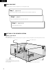
ENGLISH 2 CAUTIONS ON INSTALLATION 0.3 ft (10 cm) or more Noise or disturbance of the picture may be generated if this unit or any other electronic equipment using microprocessors is used near a tuner or TV. If this happens, take the following steps: • Install this unit as far as possible from the tuner or TV. • Set the antenna wires from the tuner or TV away from this unit’s power cord and input/output connection cords.
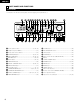
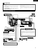
ENGLISH 5 PART NAMES AND FUNCTIONS Front Panel • For details on the functions of these parts, refer to the pages given in parentheses ( ). #0 @9 @8 @7 @6 @5 @4 @3 @2 @1 @0 !9 !8 !7 !6 B q w e r t y u q Power operation switch ..............................................(17, 24, 39) w Headphones jack (PHONES)....................................................(27) e Preset station selector buttons ...............................................(41) r SPEAKER A/B buttons.............................
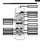
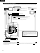
ENGLISH Remote control unit • For details on the functions of these parts, refer to the pages given in parentheses ( ). Remote control signal transmitter .........................................(15) MD/CDR CD Mode selector switch ............(16, 21, 22) AUDIO POWER TV VCR AVR/AVC VIDEO DVD/VDP ON OFF 1 V. AUX VCR 4 5 8 3 6 7 TUNER SHIFT 9 SURROUND MODE DVD/VDP 2 TV/DBS INPUT MODE CDR / TAPE INPUT MODE button ...................(25, 28) CD 6 7 Preset station select buttons....
ENGLISH 6 READ THIS FIRST This AV Surround Receiver must be setup before use. Following these steps. Step 1 (page 8 to 14) Choose the best location to setup the Speakers and connecting the components. Step 2 (page 15) Next, insert the batteries into the remote control unit. Step 3 (page 16 to 20) Finally, setting up the system.
ENGLISH 8 CONNECTIONS • Do not plug in the power cord until all connections have been completed. • Be sure to connect the left and right channels properly (left with left, right with right). • Insert the plugs securely. Incomplete connections will result in the generation of noise. • Use the AC OUTLETS for audio equipment only. Do not use them for hair driers, etc.
ENGLISH Connecting the video equipments To connect the video signal, connect using a 75 Ω/ohms video signal cable cord. Using an improper cable can result in a drop in sound quality. TV or DBS tuner AUDIO R R OUT L Connecting a TV/DBS tuner TV/DBS • Connect the TV’s or DBS tuner’s video output jack (VIDEO OUTPUT) to the VIDEO (yellow) TV/DBS IN jack using a 75 Ω/ohms video coaxial pin plug cord.
ENGLISH Connecting a TV game equipment TV game AUDIO L R L R L • Connect the TV game equipment’s output jacks to this unit’s V. AUX INPUT lacks. VIDEO VIDEO OUT R Connecting a video camera equipment Video camera AUDIO R L R L • Connect the video camera equipment’s output jacks to this unit’s V. AUX INPUT lacks. VIDEO VIDEO OUT The V. AUX terminal is covered with a cap. Remove this cap in order to use the terminal. (See page 4 for instructions on removing the cap.
ENGLISH Connecting the antenna terminals AM LOOP ANTENNA (An Accessory) DIRECTION OF BROADCASTING STATION FM ANTENNA R AM LOOP ANT. 75 Ω/ohms COAXIAL CABLE FM COAX. 75 ANTENNA TERMINALS IN DIGITAL IN PRE OUT CD SUB WOOFER DVD/ VDP DVD/ VDP IN TV/ DBS TV/ DBS COAXIAL VCR FR FL CDR/ TAPE SW C VCR SR SL CDR/ TAPE OUT EXT.
ENGLISH Speaker system connections • Connect the speaker terminals with the speakers making sure that like polarities are matched (< with <, > with >). Mismatching of polarities will result in weak central sound, unclear orientation of the various instruments, and the sense of direction of the stereo being impaired.
ENGLISH Protector circuit • This unit is equipped with a high-speed protection circuit. The purpose of this circuit is to protect the speakers under circumstances such as when the output of the power amplifier is inadvertently short-circuited and a large current flows, when the temperature surrounding the unit becomes unusually high, or when the unit is used at high output over a long period which results in an extreme temperature rise.
ENGLISH 9 USING THE REMOTE CONTROL UNIT Following the procedure outlined below, insert the batteries before using the remote control unit. Range of operation of the remote control unit Point the remote control unit at the remote control sensor as shown on the diagram at the left. B 30° 30° Approx.
ENGLISH 10 SETTING UP THE SYSTEM • Once all connections with other AV components have been completed as described in “CONNECTIONS” (see pages 9 to 14), make the various settings described below on the display. These settings are required to set up the listening room’s AV system centered around the this unit. 1 Set the slide switch to “AUDIO”.
ENGLISH Before setting up the system 1 Check that all the components are correct, then press the POWER operation switch on the main unit or the POWER button on the remote control unit to turn on the power. (Main unit) 2 (Remote control unit) Press the SYSTEM button to enter the setting. *SYSTEM SET UP NOTE: Please make sure the “AUDIO” position of the slide switch on the remote control unit. 3 Press the SELECT or (down) button to switch to the speaker configuration set up.
ENGLISH NOTE: • When “Small” has been selected for the front speakers, “Large” cannot be selected for the surround speakers. 4 Use the (left) and (right) buttons to select your subwoofer setting. (Initial) YES 4 S.WOOFER (left) button Press the SELECT or setting. NO YES (right) button (down) button to enter the settings and switch to the SUBWOOFER MODE • Parameters Large…… Select this when using speakers that can fully reproduce low sounds of below 80 Hz.
ENGLISH Setting the speaker distance Input the distances from the listening position to the speakers and set the surround delay time. Preparations: Measure the distances from the listening position to the speakers (L1 to L3 on the diagram at the right).
ENGLISH Digital input setup Input the type of components connected to the digital input terminals. 1 Use the terminal. (left) and (right) buttons to set the type of device connected to the COAXIAL input (COAXIAL) (Initial) CD 9 COAX DVD TV VCR V.AUX CDR OFF DVD (left) button (right) button • Select “OFF” if nothing is connected. Press the SELECT or 2 Use the terminal. (left) and (down) button to switch the optical input (OPT) setting.
ENGLISH 11 REMOTE CONTROL UNIT Operating DENON audio components DENON remote-controllable audio components can be controlled using this unit’s remote control unit. Note that some components, however, cannot be operated with this remote control unit. MD/CDR CD AUDIO POWER TV VCR AVR/AVC VIDEO 1 DVD/VDP ON OFF 1 V. AUX VCR 4 5 2-b 3 6 7 TUNER SHIFT 9 SURROUND MODE DVD/VDP 2 0 2-c 7 2 0 2 MD/CDR VIDEO Use the buttons shown below to operate the audio component.
ENGLISH Preset memory (Video component) DENON and other makes of components can be operated by setting the preset memory for your make of video component. This remote control unit can be used to operate components of other manufacturers without using the learning function by registering the manufacturer of the component as shown on the List of Preset Codes (pages 92, 93). Operation is not possible for some models. VIDEO DVD/VDP ON OFF 1 V.
ENGLISH Operating a video component stored in the preset memory 1 Set the slide switch to “VIDEO”. CD MD/CDR AUDIO 2 VIDEO Operate the video component. • For details, refer to the component’s operating instructions. Some models cannot be operated with this remote control unit. a. For DVD player MD/CDR CD AUDIO POWER TV VCR AVR/AVC VIDEO DVD/VDP ON CD OFF 1 V.
ENGLISH 12 OPERATION Before operating Preparations: Check that all connections are proper. B 1 1 Turn on the power. Press the ON/STANDBY button on the main unit or AVR/AVC button on the remote control unit to turn on the power. 2 (Main unit) CD 1 AVR/AVC AUDIO POWER TV VCR MD/CDR • ON/STANDBY When the button is pressed, the power turns on and the display lights after approximately 1 second. When pressed again, the power turns off, the standby mode is set and the display turns off.
ENGLISH Playing the input source 1 5 MD/CDR CD AUDIO POWER TV VCR AVR/AVC VIDEO DVD/VDP ON B CD 2 3 OFF 1 V. AUX VCR 4 5 6 7 TUNER SHIFT 9 SURROUND MODE 3 TV/DBS INPUT MODE CDR / TAPE 8 DVD/VDP 2 1 0 TAPE·VCR 6 7 2 0 CHANNEL 0 3 VIDEO SELECT CD·MD/CDR·DVD/VDP DISC SKIP+ 2 3 TITLE 3 8 1 Press the button for the program source to be played. EX 1: CD 9 2 6 SYSTEM 7 SURROUND SET UP MENU CH SELECT CD MASTER VOL 5 SELECT T.
ENGLISH 3 Select the play mode. Press the SURROUND MODE button, then press the SELECT button. Input mode display One of these lights, depending on the input signal.
ENGLISH [2] Listening over headphones 1 Connect the headphones to the PHONES jack of the front panel. PHONES NOTE: To prevent hearing loss, do not raise the volume level excessively when using headphones. B 1 2 Press the SPEAKER A or B button turn the speaker off. 2 Caution: No sound is produced from the headphones when speakers A or B are turned on. [3] Turning the sound off temporarily (muting) 1 Use this to turn off the audio output temporarily. Press the MUTING button.
ENGLISH Playback using the external input (EXT. IN) jacks 1 Set the external input (EXT. IN) mode. Press the EXT. IN to switch the external input. 8 B (Main unit) (Remote control unit) Once this is selected, the input signals connected to the FL (front left), FR (front right), C (center), SL (surround left), and SR (surround right) channels of the EXT.
ENGLISH 13 SURROUND Before playing with the surround function • Before playing with the surround function, be sure to use the test tones to adjust the playback level from each speakers. This adjustment can be performed from the remote control unit, as described below. • The adjustment with the test tones is only effective in the DOLBY/DTS SURROUND modes. The adjusted playback levels for the different surround modes are automatically stored in the memory of each surround modes.
ENGLISH Dolby Surround Pro Logic II mode 1 Select the function to which the component you want to play is connected. B EX: DVD/VDP 3 (Main unit) 2 (Remote control unit) 1 Select the Dolby Surround Pro Logic II mode. Select the DOLBY PRO LOGIC II mode using the SELECT buttons. 2 4, 6 2, 5, 7 The surround mode switches when the SURROUND MODE button is pressed. Select the DOLBY PRO LOGIC II mode. MD/CDR CD AUDIO POWER TV VCR AVR/AVC VIDEO DVD/VDP ON CD SURROUND MODE 1 OFF 1 V.
ENGLISH 7 NOTE: • When making parameter settings, the display will return to the regular condition several seconds after the last button was pressed and the setting will be completed. Set the various surround parameters.
ENGLISH Dolby Digital mode (only with digital input) and DTS Surround (only with digital input) 1 Select the input source. Playback with a digital input q Select an input source set to digital (COAXIAL/OPTICAL) (see page 20). EX: DVD/VDP 1 3 3 B (Main unit) (Remote control unit) w Set the input mode to “AUTO” or DTS. 8 1 (Main unit) 2 2 2 (Remote control unit) Select the Dolby/DTS Surround mode.
ENGLISH 6 Use the (left) and (right) buttons to set the D. COMP. (Initial) OFF LOW MID HIGH D.COMP. OFF (Remote control unit) (left) button (right) button SURROUND MENU Press the SELECT or NOTE: This parameter is not displayed during DTS playback. (down) button to switch to the LFE setting. (Remote control unit) 7 Use the (left) and (right) buttons to set the LFE level. LFE 0dB (Remote control unit) SURROUND MENU • The level can be adjusted in units of 1 dB from –10 to 0 dB.
ENGLISH 14 DSP SURROUND SIMULATION • This unit is equipped with a high performance DSP (Digital Signal Processor) which uses digital signal processing to synthetically recreate the sound field. One of 7 preset surround modes can be selected according to the program source and the parameters can be adjusted according to the conditions in the listening room to achieve a more realistic, powerful sound.
ENGLISH DSP surround simulation • To operate the surround mode and surround parameters from the remote control unit. 1 Select the surround mode for the input channel. SURROUND MODE MD/CDR CD AUDIO POWER TV VCR AVR/AVC VIDEO DVD/VDP ON CD (Remote control unit) OFF 1 V.
ENGLISH (3) DELAY TIME Use the (left) and (right) buttons to set the delay time. (Initial) 0ms DELAY 30ms 110ms 30ms (Remote control unit) (left) button (right) button (4) DEFAULT To reset the settings to the factory defaults, use the (left) and (right) buttons to display “Yes”.
ENGLISH • Operating the surround mode and surround parameters from the main unit‘s panel. 1 Press the SELECT buttons to select the surround mode.
ENGLISH Surround parameters e ROOM SIZE: This sets the size of the sound field. There are five settings: “small”, “med.s” (medium-small), “medium”, “med.l” (medium-large) and “large”. “small” recreates a small sound field, “large” a large sound field. EFFECT LEVEL: This sets the strength of the surround effect. The level can be set in 15 steps from 1 to 15. When the surround mode is set to “VIRTUAL”, the effect level can be set in steps from 1 to 10. Lower the level if the sound seems distorted.
ENGLISH 15 LISTENING TO THE RADIO Auto preset memory This unit is equipped with a function for automatically searching for FM broadcast stations and storing them in the preset memory. 1 1 When the main unit’s power operation switch turn on while pressing the set’s MEMORY button the unit automatically begins searching for FM broadcast stations. 2 When the first FM broadcast station is found, that station is stored in the preset memory at channel A1.
ENGLISH Auto tuning 1 3 4 1 Set the input function to “TUNER”. 2 Watching the display, press the BAND button to select the desired band (AM or FM). 3 Press the MODE button to set the auto tuning mode. B 2 Lit 4 Press the TUNING UP or DOWN button. • Automatic searching begins, then stops when a station is tuned in. NOTE: • When in the auto tuning mode on the FM band, the “STEREO” indicator lights on the display when a stereo broadcast is tuned in.
ENGLISH Preset stations 2 3 Preparations: Use the “Auto tuning” or “Manual tuning” operation to tune in the station to be preset in the memory. 1, 4 B 1 Press the MEMORY button. (Main unit) V. AUX VCR 3 4 INPUT MODE CDR / TAPE 7 SURROUND MODE 8 TV/DBS 5 6 TUNER SHIFT 9 Press the SHIFT button and select the desired memory block (A to E).
ENGLISH 16 LAST FUNCTION MEMORY • This unit is equipped with a last function memory which stores the input and output setting conditions as they were immediately before the power is switched off. • The unit is also equipped with a back-up memory. This function provides approximately one week of memory storage when the main unit’s power switch is off and with the power cord disconnected.
ENGLISH 18 ADDITIONAL INFORMATION Speaker setting examples Here we describe a number of speaker settings for different purposes. Use these examples as guides to set up your system according to the type of speakers used and the main usage purpose. (1) Basic setting Use this setting if your main purpose is to listen to movie music and when using one set (two speakers) of regular single-way or two-way speakers as the surround speakers.
ENGLISH 2 Dolby Digital and Dolby Pro Logic Dolby Digital Dolby Pro Logic No. recorded channels (elements) 5.1 ch 2 ch No. playback channels 5.1 ch 4 ch L, R, C, SL, SR, SW L, R, C, S (SW - recommended) Digital discrete processing Dolby Digital (AC-3) encoding/decoding Analog matrix processing Dolby Surround 20 kHz 7 kHz Comparison of home surround systems Playback channels (max.
ENGLISH DTS Digital Surround Digital Theater Surround (also called simply DTS) is a multi-channel digital signal format developed by Digital Theater Systems. DTS offers the same “5.1” playback channels as Dolby Digital (front left, front right and center, surround left and surround right) as well as the stereo 2-channel mode. The signals for the different channels are fully independent, eliminating the risk of deterioration of sound quality due to interference between signals, crosstalk, etc.
ENGLISH 19 TROUBLESHOOTING If a problem should arise,first check the following. 1. Are the connections correct ? 2. Have you operated the receiver according to the Operating Instructions ? 3. Are the speakers, turntable and other components operating property ? If this unit is not operating properly, check the items listed in the table below. Should the problem persist, there may be a malfunction. Disconnect the power immediately and contact your store of purchase. Symptom Remote control unit.
ENGLISH 20 SPECIFICATIONS 2 Audio section • Power amplifier Rated output: 70 W + 70 W (8 Ω/ohms, 100 W + 100 W (6 Ω/ohms, Center: 70 W (8 Ω/ohms, 100 W (6 Ω/ohms, Surround: 70 W + 70 W (8 Ω/ohms, 100 W + 100 W (6 Ω/ohms, Front: A or B 16 to 16 Ω/ohms A+B 12 to 16 Ω/ohms Center/Surround: 16 to 16 Ω/ohms Front: Output terminals: • Analog LINE input - SPEAKER OUT Input sensitivity / input impedance: Frequency response: S/N ratio: 20 Hz ~ 20 kHz with 0.08% T.H.D.) 1 kHz with 0.7% T.H.D.
ENGLISH FRANCAIS LIST OF PRESET CODES / LISTE DE CODES PRÉRÉGLÉS DVD Denon *[11], 12 Hitachi *[01], 02, 03, 04, 05 Hitachi 14 Instant Replay 21, 04 JVC 17 Itt/Nokia 08 Onkyo 13, 15, 16 JC Penny 02, 05, 07, 08, 09, 21 Panasonic 12, 18 JVC 07, 09, 28, 29, 30, 31 Philips 24 Kendo 11 Pioneer 19, 20, 21 Kenwood 07, 09, 11 RCA 23 Loewe 11, 26 Samsung 22 Luxor 10 Sony 25 LXI 02, 08, 11, 12, 25 Toshiba 13 Magnavox 04, 19, 21 Yamaha 12, 26 Marantz 07, 09 Marta 11 V
FRANCAIS Tatung 07, 09 LXI 03, 07, 16, 17, 21 Teac 07, 09, 12 Magnavox 03, 04, 16 Technics 04, 21 Matsui 09 Telefunken 54, 55 Mitsubishi 03, 05, 33, 34 Thorn 08, 11 NEC 03, 34 Toshiba 24, 41, 59 Nokia 28, 29 Universum 11, 20, 54 Nokia Oceanic 29 W.
14-14, AKASAKA 4-CHOME, MINATO-KU, TOKYO 107-8011, JAPAN Telephone: (03) 3584-8111 Printed in China 511 3782 003