AV SURROUND RECEIVER AVR-1707 OPERATING INSTRUCTIONS
ENGLISH SAFETY INSTRUCTIONS ¢SAFETY PRECAUTIONS CAUTION RISK OF ELECTRIC SHOCK DO NOT OPEN CAUTION: TO REDUCE THE RISK OF ELECTRIC SHOCK, DO NOT REMOVE COVER (OR BACK). NO USER-SERVICEABLE PARTS INSIDE. REFER SERVICING TO QUALIFIED SERVICE PERSONNEL.
ENGLISH FCC INFORMATION (For US customers) ¢NOTE ON USE 1. PRODUCT This product complies with Part 15 of the FCC Rules. Operation is subject to the following two conditions: (1) this product may not cause harmful interference, and (2) this product must accept any interference received, including interference that may cause undesired operation. 2. IMPORTANT NOTICE: DO NOT MODIFY THIS PRODUCT This product, when installed as indicated in the instructions contained in this manual, meets FCC requirements.
ENGLISH Thank you for choosing the DENON AVR-1707 AV Surround Receiver. This remarkable component has been engineered to provide superb surround sound listening with home theater sources such as DVD, as well as providing outstanding high fidelity reproduction of your favorite music sources. As this product is provided with an immense array of features, we recommend that before you begin hookup and operation that you review the contents of this manual before proceeding.
ENGLISH Advanced Setup – Part 1 System setup items and default values·······························38, 39 Navigating through the System Setup items ···························40 About the front display································································40 Input Setup Setting the Digital In Assignment ················································41 Setting the iPod Assignment ······················································41 Setting the Component In Assignment ·························
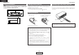
ENGLISH Getting Started Getting Started Cautions on installation About the remote control unit Note: For heat dispersal, do not install this unit in a confined space such as a bookcase or similar enclosure. In addition to controlling the AVR-1707, the attached remote control unit (RC-1048) can also be used to control the following products: q DENON component products w Component products other than DENON: • Set using the preset memory function ( page 48).
ENGLISH Getting Started Getting Started !6 Cursor buttons (D, H) ·························(22, 40) Part names and functions !7 MASTER VOLUME control knob··············(19) !8 TUNING buttons (•, ª) ·····························(31) !9 STATUS button ··········································(20) @0 DIMMER button ·········································(20) @1 VIDEO SELECT button ······························(33) @2 OUTPUT indicators······························(22, 36) @3 Display For details on the fu
ENGLISH Getting Started Getting Started Rear panel Remote control unit !4 !3 !2 !1 !0 o i [ Front ] u y Remote control signal transmitter ························(3) Indicator ····················(48, 52) Power buttons··········(10, 50) Input source selector buttons ····························(19) q w e r Tuner system/System buttons······················(31, 32) t System buttons········(50, 51) q PRE OUT terminal········································(8) w EXT.
ENGLISH Getting Started Getting Started [ Rear ] ZONE2 buttons···············(36) MAIN buttons ·················(36) Input source selector/ Number buttons·······(19, 51) SURROUND MODE buttons······················(21, 29) Tuner system/System buttons······················(31, 51) TEST TONE/DISPLAY button························(47, 51) Cursor buttons ···(11, 22, 51) SYSTEM SETUP/SETUP button························(40, 51) SURROUND PARAMETER/ AUDIO button···········(22, 51) ENTER button···········(3
ENGLISH Easy Setup Procedure Speaker layout [Basic layout] Easy Setup Procedure Example of basic layout with eight speakers and a monitor. • This section contains the basic steps necessary to configure the AVR-1707 according to your listening room environment and the source equipment and loudspeakers you are using. • To set the sound field manually ( page 45). Subwoofer Center speaker Surround back speaker Easy to setup flow Placing the speakers. Auto setup flow Connecting the speakers.
ENGLISH Easy Setup Procedure Easy Setup Procedure ¢ Connections Speaker connections Connect the speaker terminals with the speakers making sure that like polarities are matched (< with <, > with >). NOTE: When making connections, take care that none of the individual conductors of the speaker cable come in contact with adjacent terminals, with other speaker cable conductors, or with the rear panel and screws. NEVER touch the speaker terminals when the power is on.
ENGLISH Easy Setup Procedure Easy Setup Procedure • For best picture quality (especially with progressive DVD and other high definition sources), choose the component video connection to your monitor. S-Video and composite video outputs are also provided if your monitor does not have component video inputs. Connecting a DVD player and monitor • To connect the video output from the DVD player to the AVR-1707, you only need to choose one connection type.
ENGLISH Easy Setup Procedure Easy Setup Procedure w Before performing the Auto Setup procedure Auto Setup The AVR-1707’s auto setup use the attached microphone to measure the acoustic properties in the room and automatically make the optimum settings. • To make the sound field settings manually ( D H F G page 45). q Connecting a microphone the attached setup microphone to . 1 Turn on your subwoofer.
ENGLISH Easy Setup Procedure Easy Setup Procedure r Starting Auto Setup 2 Press D H to select “Store”, then press F. 1 Press F to start the Auto Setup. Store: Store the checked measurement values. All parameters are stored. • Start the measurements. Measurement of each channel is performed as follows: 1 FL FR C 2 SW SL SR SBL SBR 1: The subwoofer speaker is measured twice. 2: Not displayed when “ZONE2” is set at “Setting the Power Amplifier Assignment” ( page 43).
ENGLISH Easy Setup Procedure Easy Setup Procedure Error messages An error message is displayed if the measurements could not be completed automatically due to the speaker layout, the measuring environment, etc. Please check the following matters, reset the pertinent items, and measure again. Be sure to turn off the AVR-1707’s power before checking the speaker connections.
ENGLISH Connecting Other Sources Cable indications The video conversion function With the AVR-1707, the Video signal and the S-Video signal which were inputted are mutually converted. And also the Video signal and the S-Video signal which were inputted are converted into a higher quality. The hookup diagrams on the subsequent pages assume the use of the following optional connection cables (not supplied).
ENGLISH Connecting Other Sources Connecting Other Sources Connecting a TV/DBS tuner Connecting the external inputs (EXT. IN) terminals • These terminals are for inputting multi-channel audio signals from an outboard decoder, or a component with a different type of multi-channel decoder, such as a DVD-Audio player, or a multi-channel Super Audio CD player, or other future multi-channel sound format decoder. • The video signal connection is the same as that for a DVD player ( page 9).
ENGLISH Connecting Other Sources Connecting Other Sources Connecting a CD player Connecting a VCR To connect the digital audio output from the CD player, you can choose from either the coaxial or optical connections. If you choose to use the optical connection, it needs to be assigned. For more information about Digital Input Assignment ( page 41). • For best picture quality choose the component video connection to your VCR. S-Video and composite video outputs are also provided.
ENGLISH Connecting Other Sources Connecting Other Sources Connecting the antenna terminals NOTE: • Do not connect two FM antennas simultaneously. • Even if an external AM antenna is used, do not disconnect the AM loop antenna. • Make sure the AM loop antenna lead terminals do not touch metal parts of the panel. An FM antenna cable plug can be connected directly.
ENGLISH Connecting Other Sources Connecting the Connecting Other Sources iPod® Connecting the MULTI ZONE terminals When using an iPod, you must connect the Control Dock for iPod (ASD-1R, sold separately) and the DOCK CONTROL jack on the AVR-1707 with a mini-jack and assign the iPod to any AUDIO and/or S-VIDEO terminal(s). The diagram below shows an example of connections for when the iPod is assigned to the DVD/VDP terminal. For instructions on operations using the MULTI ZONE functions ( page 36).
ENGLISH Connecting Other Sources Connecting Other Sources ZONE2 speaker out connections Connecting the power supply cord • When the surround back’s power amplifier is assigned to the ZONE2 output channel at Power Amplifier Assignment mode, the surround back speaker terminals can be used as the ZONE2 speaker out terminals ( page 36). • The connections diagram below is an example for when the surround back speaker is assigned to the ZONE2 stereo 2 channel.
ENGLISH INPUT MODE STATUS INPUT SELECTOR DIMMER VOLUME Basic Operation Playing the input source 1 4 Use VOLUME to adjust the volume. Use INPUT SELECTOR to select the input source you want to play. 2 Press INPUT MODE. SURROUND PARAMETER AUTO PCM EXT. IN DTS INPUT SELECTOR [MUTING] DIMMER STATUS AUTO (All auto mode): The type of input signal is detected and the AVR-1707’s surround mode is switched automatically.
ENGLISH Basic Operation Basic Operation Turning the sound off temporarily (MUTING) Checking the currently playing program source, etc. Press [MUTING]. You can adjust the muting level ( page 44). Using the surround modes Types of surround modes and their features Press STATUS. • The current program source and various settings are indicated on the display. The AVR-1707 is equipped with many surround modes.
ENGLISH Basic Operation Sources recorded in stereo Sources recorded in monaural Basic Operation Selecting the play mode (DIRECT/STEREO) INPUT MODE STATUS F G, ENTER DIRECT / STEREO • Effective for achieving pure playback. • If there is no need for tone control or distribution of the low frequencies in function of the speaker configuration, select the DIRECT mode to achieve the best sound quality. ¢ DIRECT mode This mode is for playing with high quality sound.
ENGLISH Basic Operation Basic Operation Selecting the Dolby Digital and DTS Surround mode (only with digital input) an input source for which digital (COAXIAL or 1 Select OPTICAL) is set ( page 41). D.COMP.: The dynamic range is compressed. Select one of 4 modes: “OFF”, “LOW”, “MID” (middle) or “HIGH”. Effective source / mode Dolby Digital / DTS (For DTS sources, only displayed for compatible software.) 2 Press INPUT MODE to select “AUTO”. [STANDARD] to select “STANDARD (Dolby/DTS 3 Press Surround)”.
ENGLISH Basic Operation Basic Operation F G, ENTER Selecting the Dolby Pro Logic IIx (Pro Logic II) mode It is possible to play analog input signals and digital input signals (2channels) in the surround mode. This mode is optimal for playing program sources recorded in Dolby Surround. 5 Press D H to select the item, then press F G to set. The mode switches as shown below each time the button is pressed. • When the Cinema mode: CINEMA EQ MODE CINEMA 1 Press [STANDARD] to select “DOLBY PLIIx”.
ENGLISH Basic Operation Basic Operation Selecting the DTS NEO:6 mode It is possible to play analog input signals and digital input signals (2channels) in the surround mode. 1 Press [STANDARD] to select “DTS NEO:6”. DOLBY PLIIx DTS NEO:6 NEURAL SURROUND 2 Play a program source. 3 Press SURROUND PARAMETER. 4 Press F G to select the play mode. CINEMA: This mode is optimum for playing movies.
ENGLISH Basic Operation Basic Operation Surround modes and parameters Signals and adjustability in the different modes Parameter (default values are shown in parentheses) Channel output Surround Mode STEREO EXT.
ENGLISH Basic Operation Basic Operation ¢ Differences in surround mode names depending on the input signals Button Input signals DTS Surround Mode STANDARD DTS SURROUND DTS ES DSCRT6.1 DTS ES MTRX6.
ENGLISH Basic Operation Basic Operation Button Input signals DTS Surround Mode DIRECT DIRECT DSP SIMULATION 5CH/7CH STEREO MONO MOVIE ROCK ARENA JAZZ CLUB VIDEO GAME MATRIX VIRTUAL STEREO STEREO Note *1 DOLBY DIGITAL DOLBY DOLBY DIGITAL EX DIGITAL (With no Flag) (5.1ch) DOLBY DIGITAL (2ch) DVD-Audio (multi ch) DVD-Audio (2ch) 176.
ENGLISH Basic Operation Basic Operation Using the DENON original surround modes The AVR-1707 is equipped with a high performance digital signal processor (DSP) that uses digital signal processing to recreate sound fields artificially. One of seven surround modes can be selected according to the program source and parameters can be further adjusted to achieve even more realistic sound fields.
ENGLISH Basic Operation Basic Operation Selecting the DSP surround simulation F G, SELECT/ENTER ¢ To operate the surround mode and the surround parameters from the remote control unit 1 Press [DSP SIMULATION]. MONO MOVIE 5CH/7CH STEREO ROCK ARENA VIRTUAL MATRIX , SURROUND PARAMETER DH VIDEO GAME JAZZ CLUB The 5CH/7CH STEREO mode can be selected directly by pressing [5CH/7CH STEREO]. SB CH OUT • ON: Surround back channel played.
ENGLISH Basic Operation Basic Operation ¢ When you do not want to adjust the tone Setting the tone control Adjust the bass and treble to suit your tastes. Set “Tone Defeat” to “ON” at step 3 in “Adjusting the tone”. ¢ Adjusting the tone 1 Press SURROUND PARAMETER. 2 Press D H to select “TONE DEF. ON”. In the direct mode, “TONE” cannot be selected. Adjusting the speaker volume 1 2 Press CH SELECT to select the speaker. Press CH SELECT. 3 F G] to adjust the volume.
ENGLISH Basic Operation Basic Operation BAND Auto tuning SHIFT Preset memory to select “TUNER” or press the “Auto tuning” or “Manual tuning” operation 1 Use 1 Use [TUNER]. to tune in the station to be preset in the memory. 2 Press BAND to select “AM”, “FM” or “XM”. When listening to the XM Satellite Radio ( CHANNEL SHIFT [FM/AM] TUNING STATUS CHANNEL [XM RADIO] page 32). 3 Press [MODE] to set the auto tuning mode. 2 Press [MEMORY].
ENGLISH Basic Operation XM Satellite Radio AVR-1707 is the XM Ready receiver. You can receive XM® Satellite Radio by connecting to the XM Passport System (sold separately) and subscribing to the XM service. ¢ Introducing XM Satellite Radio There’s a world of audio listening pleasure beyond AM and FM. XM Satellite Radio. Select from over 170 channels of music, news, sports, comedy, talk, and entertainment. Coast-to-coast coverage. Digital quality sound. With all music channels 100% commercial free.
ENGLISH Advanced Operation INPUT SELECTOR VIDEO SELECT Night mode Calling the settings out The night mode can be set when playing Dolby Digital sources. The dialogues are easier to hear at night and when listening with the volume low. Press at which the settings you want to call out are stored. Press [NIGHT]. • Canceling night mode: Press [NIGHT] again. • When the night mode is set to “ON”, the “D.COMP” surround parameter can not be selected.
ENGLISH Advanced Operation Playing the Advanced Operation iPod® Listening to music in the Browse mode The music recorded on the iPod can be played when using a Control Dock for iPod (ASD-1R, sold separately). The iPod can be controlled using the buttons on the main unit and the remote control unit. 1 D H] to select the music file, then press [ENTER] Press [D G]. or [G F] to return to the music menu screen. Press [F iPod is a trademark of Apple Computer, Inc., registered in the U.S.
ENGLISH Advanced Operation Advanced Operation Viewing still pictures and videos (only for iPods equipped with the slideshow / video function) Use this procedure to view photo and video data stored on the iPod on a monitor. Press [MODE] for at least 2 seconds to switch from the 1 Browse mode to the Remote mode. • “Remote iPod” is displayed on the AVR-1707’s display. [OFF] [CHANNEL] [INPUT SELECTOR] D H] to select Watching the iPod’s screen, press [D 2 “Photos” G].
ENGLISH Advanced Operation Advanced Operation Multi zone music entertainment system • ZONE2 speaker out can be used when “ZONE2” is selected at “Power Amp Assignment”. In this case, surround back speaker out cannot be used for MAIN ZONE. • When a sold separately room-to-room remote control unit (DENON RC-616, 617 or 618) is wired and connected between the MAIN ZONE and ZONE2, the remote-controllable devices in the MAIN ZONE can be controlled from ZONE2 using the remote control unit.
ENGLISH Advanced Operation INPUT SELECTOR Advanced Operation Recording the program source (recording the source currently being monitored) 1 Select the input source to be played. 2 Select the input mode and play (surround) mode. 3 Start recording on the tape or video deck. For instructions, refer to the component’s operating instructions.
ENGLISH Advanced Setup – Part 1 System setup items and default values 1. Speaker Setup Speaker Item No. Setup 1~6 7 8 ~ 15 2. Input Setup Input Items Speaker Configuration mode Automatically set the output component and properties for the various channels according to the combination of speakers to be actually used for surround playback. Subwoofer Mode Setup Select the method of playback of the subwoofer for playing the low bass signals.
ENGLISH Advanced Setup – Part 1 3. Option Setup Option Advanced Setup – Part 1 Item No. Setup Items Default settings Page S. Back 43 Vol.Limit = OFF P. On Lev. = LAST Mute Lev. = FULL 44 Power Amp Assignment mode To suit your preference, a surround back channel’s power amplifier can be assigned to the front channel (“Front A” or “Front B”) for bi-amp playback, ZONE2. 2~4 Volume Control mode This sets the volume level of output.
ENGLISH Advanced Setup – Part 1 Advanced Setup – Part 1 SYSTEM SETUP Use System Setup to customize a variety of settings to suit your listening environment. For the contents of a system menu and the initial setting of this unit ( page 38, 39). Navigating through the System Setup items F G, ENTER D H 1 Press SYSTEM SETUP, then press ENTER. F G to select the item you want to set, then 2 Press press ENTER.
ENGLISH Advanced Setup – Part 1 Advanced Setup – Part 1 Input Setup Setting the iPod Assignment Setting the Digital In Assignment This assigns the different input sources for the digital input terminals. It is possible to assign the Control Dock for iPod’s (ASD-1R, sold separately) audio and video signals to any input terminals on the AVR1707 and play them. 1 1 Press F G to select “2. In”, then press ENTER. D H to select the input terminals, then press F 2 Press G to set.
ENGLISH Advanced Setup – Part 1 Advanced Setup – Part 1 Setting the Video Convert Setting the Audio Delay Setting the EXT. IN Subwoofer Level This sets whether or not to use the video conversion function. Adjust the time delay between the video and audio signals. 1 Press F G to set. 1 Press F G to set. ON, OFF: Select “ON” to use the video conversion function, “OFF” if you do not want to use it. ENTER or H to enter the setting and switch to 2 Press the Audio Delay setting.
ENGLISH Advanced Setup – Part 1 Advanced Setup – Part 1 Setting the Auto Preset Memory Up to 56 FM stations can be preset automatically ( Option Setup page 30). 1 Press F to start. • “CH” blinks on the display and searching begins. • “Completed” appears once searching is completed. Front Bi-Amp connections Setting the Power Amplifier Assignment To suit your preference, a surround back channel’s power amplifier can be assigned to the front channel (“Front A” or “Front B”) for biamp playback, ZONE2.
ENGLISH Advanced Setup – Part 1 Setting the Volume Control Advanced Setup – Part 1 1 This sets the volume level of output. 2 Limit -10dB 1 Press D H to select the item, then press F G to set. 3 P.On LAST 4 Mute FULL Volume Limit: Set the volume’s upper limit. • 0 dB, –10 dB, –20 dB: The volume cannot be increased above the selected levels. • OFF: If you do not want to set a volume limit, select “OFF”.
ENGLISH Advanced Setup – Part 1 Setting the Auto Surround Mode Advanced Setup – Part 2 Set whether or not to store the surround mode last played for the input signal. The surround mode used at last for the three types of input signals shown below is stored in the memory, and the signal is automatically played with that surround mode the next time it is input.
ENGLISH Advanced Setup – Part 2 Advanced Setup – Part 2 Setting the Subwoofer Mode Setup 1 Select the method of playback of the subwoofer for playing the low bass signals. Speaker 2 Setup 1 Press F G to set. 1 6 3 Front 7 SW Yes Mode Norm • Select “Large” or “Small” not according to the actual size of the speaker but according to the speaker’s capacity for playing low frequency (bass sound below the frequency set for the Crossover Frequency) signals.
ENGLISH Advanced Setup – Part 2 Advanced Setup – Part 2 Setting the Test Tone • The distance changes in units of 1 foot (0.1 meters) each time the button is pressed. Select the value closest to the measured distance. • Please note that the difference of distance for every speaker should be 20 ft (6.0 m) or less. Setting the Crossover Frequency Set the frequency (Hz) below which the bass sound of the various speakers is to be output from the subwoofer.
ENGLISH Operating the remote control unit Operating DENON audio components [MODE SELECTOR 1] [MODE SELECTOR 2] 3 Press [ZONE2 OFF] and [MAIN ON] at the same time. • The indicator starts flashing. 1 Referring to the included list of preset codes, press 4 [NUMBER] to input the preset code (a 3-digit number) Set [MODE SELECTOR 2] to the position for the 2 component for the manufacturer of the component whose signals to be operated (CD, CD-R/MD or TAPE). Set [MODE SELECTOR 1] to “AUDIO”.
ENGLISH Operating the remote control unit Operating the remote control unit [ON/SOURCE] [OFF] [SHIFT] [MODE SELECTOR 1] [CHANNEL + –] [MODE SELECTOR 2] [NUMBER] (0 ~ 9, +10) [2], [1], [3], [6 7], [VCR CH + –], [8 9], [0], [DISC SKIP +] [TV/VCR] [SETUP], [DISPLAY], [ENTER], [D H F G], [AUDIO], [RETURN], [MENU] Operating a component stored in the preset memory 1 Set [MODE SELECTOR 1] to “AUDIO” or “VIDEO”.
ENGLISH Operating the remote control unit Operating the remote control unit ¢ Functions of buttons for the different devices [Front] Device operated CD player CD recorder MD recorder MODE SELECTOR 1 Tape deck DVD player Video disc player Video deck Satellite tuner Cable TV TV (Monitor) VIDEO AUDIO CD-R / MD DVD / VDP TAPE DBS / CABLE VCR TV MODE SELECTOR 2 CD OFF – – – – Power off – – – – – ON / SOURCE – – – – Power on Power on /Standby Power on /Standby Power on /S
ENGLISH Operating the remote control unit Operating the remote control unit [Rear] Device operated CD player CD recorder MODE SELECTOR 1 MD recorder Tape deck DVD player Video disc player Video deck AUDIO Satellite tuner Cable TV TV (Monitor) VIDEO MODE SELECTOR 2 CD NUMBER (0 ~ 9, +10) – – – – Number input / Track selection Number input / Track selection – Channels Channels Channels TV/ VCR – – – – Input mode selection Input mode selection Input mode selection Input mod
ENGLISH Operating the remote control unit Operating the remote control unit Setting the punch through function [MODE SELECTOR 1] [MODE SELECTOR 2] “Punch Through” is a function allowing you to operate 1, 2, 6, 7, 8 and 9 on CD, TAPE, CD-R/MD, DVD/VDP or VCR components when in the DBS/CABLE or TV mode. By default, nothing is set. 1 Set [MODE SELECTOR 1] to “VIDEO”. Set [MODE SELECTOR 2] to the component to be 2 registered (DBS/ CABLE or TV). 3 Press [MEMORY] and [INPUT MODE] at the same time.
ENGLISH Additional Information We recommend using two speakers. When using dipolar speakers in particular, be sure to use two speakers. Surround back speakers Sound position directly to the rear can be achieved easily by adding a surround back speaker to a 5.1-channel system.
ENGLISH Additional Information Surround Additional Information DTS NEO:6 surround DTS Digital Surround DTS Digital Surround is a digital surround format developed by Digital Theater Systems of the United States. The number of playback channels and the playing band is the same as for Dolby Digital (5.1-channels).
ENGLISH Troubleshooting Symptom Troubleshooting No sound is produced from subwoofer. If a problem should arise, first check the following. 1. Are the connections correct? 2. Have you operated the receiver according to the Operating Instructions? 3. Are the speakers and other components operating properly? If this unit is not operating properly, check the items listed in the table below. Should the problem persist, there may be a malfunction.
ENGLISH Troubleshooting Troubleshooting Symptom Cause Measures Page “OFF AIR” is displayed in the XM mode. • The selected channel is not currently • Select the another channel. broadcasting. 32 Receiving only XM channels 0 and 1. • The XM Tuner is not activated. 32 • Contact XM Radio.
ENGLISH ¢ List of preset codes DVD ASA 042 Go Video 047, 048 Minolta 013, 023 Denon 014, *[111] Asha 087 Goldstar 000, 006, 012, 062, 088 Mitsubishi 001, 003, 008, 013, 014, Aiwa 009 Audio Dynamic 005, 085 Gradiente 094 Hitachi 010 Audiovox 088 Grundig 042 JVC 006, 011 Beaumark 087 Harley Davidson 094 Motorola Konka 012, 013 Broksonic 086, 093 Harman Kardon 040, 062 Montgomery Ward Magnavox 005 Calix 088 Hi-Q 091 Mitsubishi 004 Candle 006, 087, 088, 089, 09
ENGLISH Radix 088 Technics 024, 049 Bell & Howell 045, 118 Fujitsu 004, 062 Randex 088 Teknika 009, 010, 022, 049, 088, Bradford 061 Funai 004, 062 RCA Realistic 094 Brockwood 003, 047 Futuretech 004 063, 064, 065, 073, 080, TMK 087, 092 Candle 003, 030, 031, 032, 038, GE 020, 036, 037, 040, 044, 082, 087 Toshiba 013, 017, 020, 041, 059, 007, 013, 019, 023, 058, 047, 049, 050, 122 058, 066, 088, 119, 120, 089, 098, 099, 117 Capehart 003 007, 087, 088 Celebrity 046 U
ENGLISH Magnavox 005, 010, 017, 030, 033, Philips 038, 050, 056, 071, 078, 005, 015, 017, 050, 051, Squareview 004 Eastern 015 056, 078, 087, 088, 089, Supre-Macy 032, 122 Garrard 011 131, 132, 147 Supreme 046 Gemini 030, 033, 034 110, 127, 131, 132, 145 Pioneer 124, 128, 142 Sylvania 005, 010, 017, 030, 078, General Instrument 030, 031, 032 015, 017, 071, 080 Portland 054 079, 085, 089, 101, 127, Hytex 006 Matsui 027 Price Club 095 131, 132, 145, 155 Jasco 011 Memorex
ENGLISH 062, 066 Magnavox 006, 015, 035 Optimus 007, 008 GE 048, 055, 056 Marantz 016, 028, 035 Panasonic 012 General Instruments 039, 040, 041 MCS 016, 024 Philips 002 Grundig 070, 071, 072, 073 Onkyo 025, 027 Pioneer 007, 008, 009 Hitachi 058, 059 Optimus 017, 020, 021, 022, 023 Sony 013, 014, 015 Hughes Network 063, 064, 065, 069 Philips 014, 032, 033, 035 Technics 012 JVC 057 Pioneer 006, 022, 030 Victor 004 Kathrein 074, 075, 076, 083 Sears 006 Wards 007 M
TOKYO, JAPAN www.denon.com Denon Brand Company, D&M Holdings Inc.