AV SURROUND RECEIVER AVR-1802/882 OPERATING INSTRUCTIONS MODE D’EMPLOI MD/CDR CD AUDIO POWER TV VCR AVR/AVC VIDEO DVD/VDP ON PHONO CD DVD/VDP VCR-2 TV/DBS TUNER SHIFT OFF B V.AUX PRECISION AUDIO COMPONENT / AV SURROUND RECEIVER VCR-1 MASTER VOLUME AVR-1802 INPUT MODE CDR / TAPE CD PHONO DVD / VDP TUNER VCR-1 TV / DBS ON / STANDBY VCR-2 V.
ENGLISH FRANCAIS 2 SAFETY PRECAUTIONS CAUTION CAUTION TO PREVENT ELECTRIC SHOCK, MATCH WIDE BLADE OF PLUG TO WIDE SLOT, FULLY INSERT. RISK OF ELECTRIC SHOCK DO NOT OPEN CAUTION: TO REDUCE THE RISK OF ELECTRIC SHOCK, DO NOT REMOVE COVER (OR BACK). NO USER-SERVICEABLE PARTS INSIDE. REFER SERVICING TO QUALIFIED SERVICE PERSONNEL.
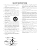
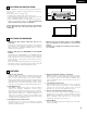
SAFETY INSTRUCTIONS 12. Power-Cord Protection – Power-supply cords should be routed so that they are not likely to be walked on or pinched by items placed upon or against them, paying particular attention to cords at plugs, convenience receptacles, and the point where they exit from the appliance. Heed Warnings – All warnings on the appliance and in the operating instructions should be adhered to. 14. Cleaning – The appliance should be cleaned only as recommended by the manufacturer. 4.
ENGLISH 2 INTRODUCTION Thank you for choosing the DENON A/V Surround receiver. This remarkable component has been engineered to provide superb surround sound listening with home theater sources such as DVD, as well as providing outstanding high fidelity reproduction of your favorite music sources. As this product is provided with an immense array of features, we recommend that before you begin hookup and operation that you review the contents of this manual before proceeding.
ENGLISH 2 CAUTIONS ON INSTALLATION 0.3 ft (10 cm) or more Noise or disturbance of the picture may be generated if this unit or any other electronic equipment using microprocessors is used near a tuner or TV. If this happens, take the following steps: • Install this unit as far as possible from the tuner or TV. • Set the antenna wires from the tuner or TV away from this unit’s power cord and input/output connection cords.
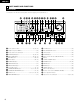
ENGLISH 5 PART NAMES AND FUNCTIONS Front Panel • For details on the functions of these parts, refer to the pages given in parentheses ( ). #0 @9 @8 @7 @6 @5 @4 @3 @2 @1 @0 !9 !8 !7 B PRECISION AUDIO COMPONENT / AV SURROUND RECEIVER CD PHONO DVD / VDP TUNER AVR-1802 !6 MASTER VOLUME VOLUME LEVEL REMOTE SENSOR SIGNAL DIGITAL CDR / TAPE VCR-1 TV / DBS ON / STANDBY VCR-2 V.
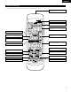
ENGLISH Remote control unit • For details on the functions of these parts, refer to the pages given in parentheses ( ). Remote control signal transmitter .........................................(16) MD/CDR CD Mode selector switch ............(17, 22, 23) AUDIO POWER TV VCR AVR/AVC VIDEO DVD/VDP ON INPUT MODE button ...................(26, 29) PHONO CD DVD/VDP OFF 1 2 3 V. AUX VCR-1 VCR-2 TV/DBS 4 5 6 7 TUNER SHIFT INPUT MODE CDR / TAPE 8 SURROUND MODE button .....................
ENGLISH 6 READ THIS FIRST This AV Surround Receiver must be setup before use. Following these steps. Step 1 (page 8 to 15) Choose the best location to setup the Speakers and connecting the components. Step 2 (page 16) Next, insert the batteries into the remote control unit. Step 3 (page 17 to 21) Finally, setting up the system.
ENGLISH 8 CONNECTIONS • Do not plug in the power cord until all connections have been completed. • Be sure to connect the left and right channels properly (left with left, right with right). • Insert the plugs securely. Incomplete connections will result in the generation of noise. • Use the AC OUTLETS for audio equipment only. Do not use them for hair driers, etc.
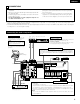
ENGLISH OUTPUT R L R OUTPUT CD player DIGITAL AUDIO COAXIAL OPTICAL CD player, etc. equipped with DIGITAL output DIGITAL AUDIO L DIGITAL jacks LINE OUT SIGNAL GND PHONO MONITOR DVD / VDP DVD / VDP TV / DBS TV/ DBS VCR-2 VCR-1 VCR-2 MONITOR S-VIDEO CENTER SUB WOOFER PREOUT VCR-1 FR FL VCR -2 OPT-1 VCR-2 SW C VCR -1 OPT-2 VCR-1 SR SL VCR -2 OPT-2 EXT. IN VCR-1 FRONT TV / DBS COAX. VCR -1 DIGITAL IN DVD/ VDP CD AM FM COAX.
ENGLISH Connecting a TV/DBS tuner TV or DBS tuner AUDIO OUT VIDEO DIGITAL OUT OUT OPTICAL L AUDIO OUT L VIDEO DIGITAL OUT OUT COAXIAL L R DVD player or video disc player (VDP) B VIDEO OUT Connecting a DVD player or a video disc player VDP • Connect the DVD player’s (video disc player’s) video output jack (VIDEO OUTPUT) to the VIDEO (yellow) DVD/VDP IN jack using a 75 Ω/ohms video coaxial pin plug cord.
ENGLISH Connecting a video component equipped with S-video jacks • When marking connections, also refer to the operating instructions of the other components. • A note on the S input jacks The input selectors for the S inputs and pin jack inputs work in conjunction with each other.
ENGLISH Connecting the antenna terminals DIRECTION OF BROADCASTING STATION AM LOOP ANTENNA (An Accessory) FM ANTENNA SIGNAL GND PHONO CDR / TAPE CDR / TAPE ANTENNA TERMINALS 75 Ω/ohms COAXIAL CABLE FEEDER CABLE LOOP ANT. CD MONITOR DVD / VDP DVD / VDP AM FM COAX. 75 TV / DBS COAX. VCR -1 FM ANTENNA ADAPTER (An Accessory) TV / DBS VCR-1 FR FL VCR -2 OPT-1 VCR-2 SW C VCR -1 OPT-2 VCR-1 SR SL VCR -2 OPT-2 EXT.
ENGLISH Speaker system connections • Connect the speaker terminals with the speakers making sure that like polarities are matched (< with <, > with >). Mismatching of polarities will result in weak central sound, unclear orientation of the various instruments, and the sense of direction of the stereo being impaired.
ENGLISH Protector circuit • This unit is equipped with a high-speed protection circuit. The purpose of this circuit is to protect the speakers under circumstances such as when the output of the power amplifier is inadvertently short-circuited and a large current flows, when the temperature surrounding the unit becomes unusually high, or when the unit is used at high output over a long period which results in an extreme temperature rise.
ENGLISH 9 USING THE REMOTE CONTROL UNIT Following the procedure outlined below, insert the batteries before using the remote control unit. Range of operation of the remote control unit Point the remote control unit at the remote control sensor as shown on the diagram at the left. B 30° 30° Approx.
ENGLISH 10 SETTING UP THE SYSTEM • Once all connections with other AV components have been completed as described in “CONNECTIONS” (see pages 9 to 15), make the various settings described below on the display. These settings are required to set up the listening room’s AV system centered around the this unit. 1 Set the slide switch to “AUDIO”.
ENGLISH Before setting up the system 1 Check that all the components are correct, then press the POWER operation switch on the main unit or the POWER button on the remote control unit to turn on the power. (Main unit) 2 (Remote control unit) Press the SYSTEM button to enter the setting. *SYSTEM SET UP NOTE: Please make sure the “AUDIO” position of the slide switch on the remote control unit. 3 Press the SELECT or (down) button to switch to the speaker configuration set up.
ENGLISH NOTE: • When “Small” has been selected for the front speakers, “Large” cannot be selected for the surround speakers. 4 Use the (left) and (right) buttons to select your subwoofer setting. (Initial) YES 4 S.WOOFER (left) button Press the SELECT or setting. NO YES (right) button (down) button to enter the settings and switch to the SUBWOOFER MODE • Parameters Large…… Select this when using speakers that can fully reproduce low sounds of below 80 Hz.
ENGLISH Setting the delay time Input the distances from the listening position to the speakers and set the surround delay time. Preparations: Measure the distances from the listening position to the speakers (L1 to L3 on the diagram at the right).
ENGLISH Digital input setup Input the type of components connected to the digital input terminals. 1 Use the terminal. (left) and (right) buttons to set the type of device connected to the COAXIAL input (COAXIAL) (Initial) CD 9 COAX DVD TV VCR1 VCR2 CDR OFF DVD (left) button (right) button • Select “OFF” if nothing is connected. Press the SELECT or 2 Use the terminal. (left) and (down) button to switch the optical input 1 (OPT 1) setting.
ENGLISH 11 REMOTE CONTROL UNIT Operating DENON audio components DENON remote-controllable audio components can be controlled using this unit’s remote control unit. Note that some components, however, cannot be operated with this remote control unit. MD/CDR CD AUDIO POWER TV VCR AVR/AVC VIDEO 1 DVD/VDP ON PHONO CD DVD/VDP OFF 1 2 3 V.
ENGLISH Preset memory (Video component) DENON and other makes of components can be operated by setting the preset memory for your make of video component. This remote control unit can be used to operate components of other manufacturers without using the learning function by registering the manufacturer of the component as shown on the List of Preset Codes (pages 94, 95). Operation is not possible for some models. VIDEO DVD/VDP ON PHONO CD DVD/VDP OFF 1 2 3 V.
ENGLISH Operating a video component stored in the preset memory 1 Set the slide switch to “VIDEO”. CD MD/CDR AUDIO 2 VIDEO Operate the video component. • For details, refer to the component’s operating instructions. Some models cannot be operated with this remote control unit. a. For DVD player MD/CDR CD AUDIO POWER TV VCR AVR/AVC VIDEO DVD/VDP ON PHONO CD DVD/VDP OFF 1 2 3 V.
ENGLISH 12 OPERATION Before operating Preparations: Check that all connections are proper. B 1 1 Turn on the power. Press ON/STANDBY on the main unit or the AVR/AVC on the remote control unit to turn on the power 2 (Main unit) CD 1 AVR/AVC AUDIO POWER TV VCR • ON/STANDBY When the button is pressed, the power turns on and the display lights after approximately 1 second. When pressed again, the power turns off, the standby mode is set and the display turns off.
ENGLISH Playing the input source 1 5 MD/CDR CD AUDIO POWER TV VCR AVR/AVC B VIDEO DVD/VDP ON PHONO 2 3 CD DVD/VDP OFF 1 2 3 V. AUX VCR-1 VCR-2 TV/DBS 4 5 6 7 TUNER SHIFT INPUT MODE CDR / TAPE 8 9 SURROUND MODE 1 0 TAPE·VCR 6 7 2 0 CHANNEL 0 3 VIDEO SELECT CD·MD/CDR·DVD/VDP DISC SKIP+ 2 1 3 TITLE 3 8 Press the button for the program source to be played. EX 1: CD 9 2 6 SYSTEM 7 SURROUND SET UP MENU CH SELECT CD MASTER VOL 5 SELECT T.
ENGLISH 3 Select the play mode. Press the SURROUND MODE button, then turn SELECT knob. SELECT Input mode display One of these lights, depending on the input signal. • In the AUTO mode INPUT PCM AUTO DTS DIGITAL SURROUND MODE ANALOG • In the DIGITAL PCM mode INPUT PCM AUTO DTS DIGITAL (Main unit) (Remote control unit) To select the surround mode while adjusting the surround parameters, channel volume or tone control, press the surround mode button then operate the selector.
ENGLISH [2] Listening over headphones 1 Connect the headphones to the PHONES jack of the front panel. PHONES NOTE: To prevent hearing loss, do not raise the volume level excessively when using headphones. B 1 2 Press SPEAKER A or B to turn the speaker off. 2 Cautions: • No sound is produced from the headphones when speakers A or B are turned on. • When an external power amplifier is connected to the front preout jacks, turn off the external power amplifier’s speaker switch.
ENGLISH Playback using the external input (EXT. IN) jacks 1 Set the external input (EXT. IN) mode. Press the EXT. IN to switch the external input. 8 (Main unit) B (Remote control unit) Once this is selected, the input signals connected to the FL (front left), FR (front right), C (center), SL (surround left), and SR (surround right) channels of the EXT.
ENGLISH 13 SURROUND Before playing with the surround function • Before playing with the surround function, be sure to use the test tones to adjust the playback level from each speakers. This adjustment can be performed from the remote control unit, as described below. • The adjustment with the test tones is only effective in the DOLBY/DTS SURROUND modes. The adjusted playback levels for the different surround modes are automatically stored in the memory of each surround modes.
ENGLISH Dolby Surround Pro Logic II mode 1 Select the function to which the component you want to play is connected. B EX: DVD/VDP 3 (Main unit) 2 (Remote control unit) 1 Select the Dolby Surround Pro Logic II mode. Select the DOLBY PRO LOGIC II mode using the SELECT knob. 2 4. 6 2, 5, 7 The surround mode switches when the SURROUND MODE button is pressed. Select the DOLBY PRO LOGIC II mode.
ENGLISH 7 NOTE: • When making parameter settings, the display will return to the regular condition several seconds after the last button was pressed and the setting will be completed. Set the various surround parameters.
ENGLISH Dolby Digital mode (only with digital input) and DTS Surround (only with digital input) 1 Select the input source. 1 Playback with a digital input q Select an input source set to digital (COAXIAL/OPTICAL) (see page 21). 3 B EX: DVD/VDP 3 (Main unit) (Remote control unit) 1 4 2 2 w Set the input mode to “AUTO” or DTS. 8 MD/CDR CD AUDIO POWER TV VCR AVR/AVC VIDEO DVD/VDP ON (Main unit) 2 (Remote control unit) PHONO Select the Dolby/DTS Surround mode.
ENGLISH SURROUND MENU Press SURROUND or (down) button to switch to the D.COMP. setting. (Remote control unit) 5 Use (left) and (right) buttons to set the D. COMP. (Initial) OFF SURROUND MENU LOW (left) button Press SURROUND or (down) button to switch to the LFE setting. (Remote control unit) 6 MID HIGH D.COMP. OFF (Remote control unit) Use (left) and (right) button NOTE: This parameter is not displayed during DTS playback. (right) buttons to set the LFE level.
ENGLISH 14 DSP SURROUND SIMULATION • This unit is equipped with a high performance DSP (Digital Signal Processor) which uses digital signal processing to synthetically recreate the sound field. One of 7 preset surround modes can be selected according to the program source and the parameters can be adjusted according to the conditions in the listening room to achieve a more realistic, powerful sound.
ENGLISH DSP surround simulation • To operate the surround mode and surround parameters from the remote control unit. 1 Select the surround mode for the input channel. MD/CDR CD SURROUND MODE AUDIO POWER TV VCR AVR/AVC VIDEO DVD/VDP ON PHONO (Remote control unit) CD 1 2 3 VCR-1 VCR-2 TV/DBS 4 5 INPUT MODE CDR / TAPE 8 The surround mode switches in the following order each time the SURROUND MODE button is pressed: 6 7 TUNER SHIFT 9 SURROUND MODE 1 DVD/VDP OFF V.
ENGLISH (3) DELAY TIME Use the (left) and (right) buttons to set the delay time. (Initial) 0ms DELAY 30ms 110ms 30ms (Remote control unit) (left) button (right) button (4) DEFAULT To reset the settings to the factory defaults, use the (left) and (right) buttons to display “Yes”.
ENGLISH • Operating the surround mode and surround parameters from the main unit‘s panel. 1 Turn the SELECT knob to select the surround mode.
ENGLISH Surround parameters e ROOM SIZE: This sets the size of the sound field. There are five settings: “small”, “med.s” (medium-small), “medium”, “med.l” (medium-large) and “large”. “small” recreates a small sound field, “large” a large sound field. EFFECT LEVEL: This sets the strength of the surround effect. The level can be set in 15 steps from 1 to 15. When the surround mode is set to “VIRTUAL”, the effect level can be set in steps from 1 to 10. Lower the level if the sound seems distorted.
ENGLISH 15 LISTENING TO THE RADIO Auto preset memory This unit is equipped with a function for automatically searching for FM broadcast stations and storing them in the preset memory. 1 1 When the main unit’s power operation switch turn on while pressing the set’s MEMORY button the unit automatically begins searching for FM broadcast stations. 2 When the first FM broadcast station is found, that station is stored in the preset memory at channel A1.
ENGLISH Auto tuning 1 1 Press TUNER to set the input function to “TUNER”. 3 4 B (Main unit) 2 Watching the display, press BAND to select the desired band (AM or FM). 2 4 Press TUNING UP or DOWN. (Main unit) 3 Press MODE to set the auto tuning mode. (Main unit) • Automatic searching begins, then stops when a station is tuned in. Lit (Main unit) NOTE: • When in the auto tuning mode on the FM band, the “STEREO” indicator lights on the display when a stereo broadcast is tuned in.
ENGLISH Preset stations 2 Preparations: Use the “Auto tuning” or “Manual tuning” operation to tune in the station to be preset in the memory. 1,4 3 B 1 Press MEMORY button. (Main unit) V. AUX VCR-1 VCR-2 TV/DBS 3 4 5 6 TUNER SHIFT INPUT MODE CDR / TAPE 7 SURROUND MODE 8 9 Press SHIFT button and select the desired memory block (A to E).
ENGLISH 16 LAST FUNCTION MEMORY • This unit is equipped with a last function memory which stores the input and output setting conditions as they were immediately before the power is switched off. • The unit is also equipped with a back-up memory. This function provides approximately one week of memory storage when the main unit’s power switch is off and with the power cord disconnected.
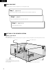
ENGLISH 18 ADDITIONAL INFORMATION Speaker setting examples Here we describe a number of speaker settings for different purposes. Use these examples as guides to set up your system according to the type of speakers used and the main usage purpose. (1) Basic setting Use this setting if your main purpose is to listen to movie music and when using one set (two speakers) of regular single-way or two-way speakers as the surround speakers.
ENGLISH 2 Dolby Digital and Dolby Pro Logic Dolby Digital Dolby Pro Logic No. recorded channels (elements) 5.1 ch 2 ch No. playback channels 5.1 ch 4 ch L, R, C, SL, SR, SW L, R, C, S (SW - recommended) Digital discrete processing Dolby Digital (AC-3) encoding/decoding Analog matrix processing Dolby Surround 20 kHz 7 kHz Comparison of home surround systems Playback channels (max.
ENGLISH DTS Digital Surround Digital Theater Surround (also called simply DTS) is a multi-channel digital signal format developed by Digital Theater Systems. DTS offers the same “5.1” playback channels as Dolby Digital (front left, front right and center, surround left and surround right) as well as the stereo 2-channel mode. The signals for the different channels are fully independent, eliminating the risk of deterioration of sound quality due to interference between signals, crosstalk, etc.
ENGLISH 19 TROUBLESHOOTING If a problem should arise,first check the following. 1. Are the connections correct ? 2. Have you operated the receiver according to the Operating Instructions ? 3. Are the speakers, turntable and other components operating property ? If this unit is not operating properly, check the items listed in the table below. Should the problem persist, there may be a malfunction. Disconnect the power immediately and contact your store of purchase. Symptom Remote control unit.
ENGLISH 20 SPECIFICATIONS 2 Audio section • Power amplifier Rated output: 80 W + 80 W (8 Ω/ohms, 115 W + 115W (6 Ω/ohms, Center: 80 W (8 Ω/ohms, 115 W (6 Ω/ohms, Surround: 80 W + 80 W (8 Ω/ohms, 115 W + 115W (6 Ω/ohms, 100 W x 2 ch (8 Ω/ohms) 145 W x 2 ch (4 Ω/ohms) 170 W x 2 ch (2 Ω/ohms) Front: A or B 16 to 16 Ω/ohms A+B 12 to 16 Ω/ohms Center/Surround: 16 to 16 Ω/ohms Front: Dynamic power: Output terminals: • Analog LINE input - PRE OUT Input sensitivity / input impedance: Frequency response: S/N r
FRANCAIS 2 INTRODUCTION Nous vous remercions d‘avoir choisi l’ampli-tuner A/V Surround de DENON. Ce remarquable composant a été fabriqué pour fournir une superbe écoute de sons d’ambiance avec des sources de cinéma domestique telles que DVD, ainsi que pour assurer une formidable reproduction haute fidélité de vos sources musicales favorites.
FRANCAIS 2 PRECAUTIONS D’INSTALLATION 10 cm (0.3 pieds) ou plus L’utilisation simultanée de cet appareil ou d’autres appareils électroniques à microprocesseur avec un tuner ou un téléviseur peut produire des parasites dans le son ou l’image. Si cela se produit, prendre les mesures suivantes: • Installer cet appareil aussi loin que possible du tuner ou du téléviseur.
FRANCAIS 5 NOMENCLATURE ET FONCTIONS Panneau avant • Pour les détails sur les fonctions de ces pièces, se reporter aux pages données entre parenthèses ( ). #0 @9 @8 @7 @6 @5 @4 @3 @2 @1 @0 !9 !8 !7 B PRECISION AUDIO COMPONENT / AV SURROUND RECEIVER CD PHONO DVD / VDP TUNER AVR-1802 !6 MASTER VOLUME VOLUME LEVEL REMOTE SENSOR SIGNAL DIGITAL CDR / TAPE VCR-1 TV / DBS ON / STANDBY VCR-2 V.
FRANCAIS Unité de télécommande • Pour les détails sur les fonctions de ces pièces, se reporter aux pages données entre parenthèses ( ). Emetteur de signaux de télécommande ..............................(61) MD/CDR CD Sélecteurs de mode ..............(62, 67, 68) AUDIO POWER TV VCR AVR/AVC VIDEO DVD/VDP ON Touche INPUT MODE ..................(71, 74) PHONO CD DVD/VDP OFF 1 2 3 V. AUX VCR-1 VCR-2 TV/DBS 4 5 6 7 TUNER SHIFT INPUT MODE CDR / TAPE 8 Touche SURROUND MODE................
FRANCAIS 6 A LIRE EN PREMIER Ce récepteur d’ambiance AV doit être réglé avant l’utilisation selon les étapes suivantes. Etape 1 (page 53 à 60) Choisir le meilleur emplacement pour l’installation des enceintes et la connexion des composants. Etape 2 (page 61) Ensuite, insérer les piles dans la télécommande. Etape 3 (page 62 à 66) Finalement, configurer le système.
FRANCAIS 8 CONNEXIONS • Ne pas brancher le cordon d’alimentation avant d’avoir terminé toutes les connexions. • Toujours connecter correctement les canaux de gauche et de droite (gauche avec la gauche et droite avec la droite). • Insérer fermement les fiches. Des connexions incomplètes peuvent générer des parasites. • N’utiliser les prises secteur (AC OUTLETS) que pour l’équipement audio. Ne pas les utiliser pour un sèche-cheveux, etc.
FRANCAIS OUTPUT R L R OUTPUT COAXIAL OPTICAL Lecteur de CD DIGITAL AUDIO Lecteur de CD, etc. équipé de sortie numérique (DIGITAL) DIGITAL AUDIO L Prises numériques (DIGITAL) LINE OUT Connecter les prises de sortie analogique (ANALOG OUTPUT) du lecteur de CD aux prises CD de cet appareil en utilisant les cordons à fiches à broche.
FRANCAIS Connexion d’un téléviseur/tuner DBS Téléviseur ou tuner DBS AUDIO OUT VIDEO DIGITAL OUT OUT OPTICAL L AUDIO R OUT VIDEO DIGITAL OUT OUT COAXIAL L B Lecteur de DVD ou lecteur de vidéo disque (VDP) L R Connexion d’un lecteur de DVD ou d’un lecteur de vidéo disque (VDP) • Connecter la prise de sortie vidéo (VIDEO OUTPUT) du lecteur de DVD (lecteur de vidéo disque) à la prise d’entrée de DVD/VDP (DVD/VDP IN) VIDEO (jaune) en utilisant un cordon à fiches à broche coaxial vidéo de 75 Ω/ohms.
FRANCAIS Connexion d’un composant vidéo équipé de prises vidéo S • Lors des connexions, se reporter également aux instructions d’utilisation des autres composants. • Remarque à propos des prises en S Les sélecteurs d’entrée pour les entrées en S et les entrées des prises à broches fonctionnent conjointement l’un avec l’autre.
FRANCAIS Connexion des bornes d’antennes DIRECTION DE STATION DE RADIODIFFUSION ANTENNE-CADRE AM (Accessoire) ANTENNE FM SIGNAL GND PHONO CDR / TAPE CDR / TAPE ANTENNA TERMINALS CABLE COAXIAL DE 75 Ω/ohms ARRIVEE Câble d’arrivée LOOP ANT. CD MONITOR DVD / VDP DVD / VDP AM FM COAX. 75 TV / DBS COAX. VCR -1 ADAPTATEUR D’ANTENNE FM (Accessoire) TV / DBS VCR-1 FR FL VCR -2 OPT-1 VCR-2 SW C VCR -1 OPT-2 VCR-1 SR SL VCR -2 OPT-2 EXT.
FRANCAIS Connexions du système d’enceintes • Connecter les bornes d’enceinte aux enceintes en respectant les polarités (< au <, > au >). Si les polarités ne sont pas respectées, un son central faible est entendu, l’orientation des divers instruments n’est pas correcte et le sens de la direction du son stéréo est détérioré.
FRANCAIS Circuit de protection • Cet appareil est équipé d’un circuit de protection haute vitesse. Le but de ce circuit est de protéger les enceintes contre des situations telles que lorsque la sortie de l’amplificateur de puissance est accidentellement court-circuitée et qu’un fort courant passe, lorsque la température avoisinant l’appareil devient anormalement élevée, ou lorsque l’appareil est utilisé à puissance élevée pendant une longue durée, ce qui entraîne une augmentation de température extrême.
FRANCAIS 9 UTILISATION DE LA TÉLÉCOMMANDE En suivant la procédure expliquée ci-dessous, insérer les piles avant d’utiliser la télécommande. Plage d’utilisation de la télécommande Diriger la télécommande vers le détecteur de télécommande de la manière indiquée sur le diagramme de gauche. B 30° 30° Approx.
FRANCAIS 10 INSTALLATION DU SYSTEME • Une fois que toutes les connexions avec les autres composants AV ont été faites comme indiqué dans “CONNEXIONS” (voir pages 54 à 60), faire les différents réglages décrits ci-dessous sur l’affichage. Ces réglages sont nécessaires pour configurer le système de chambre d’écoute AV centré autour de cette unité. 1 Régler le commutateur coulissant vers “AUDIO”.
FRANCAIS Avant de configurer le système 1 Vérifier que tous les composants sont en bon état, puis appuyez sur l’interrupteur de mise en marche POWER sur l’unité principale ou la touche POWER sur la télécommande pour allumer l’alimentation. (Unité principale) 2 (Unité de télécommande) Appuyer sur la touche SYSTEM pour accéder aux réglages. *SYSTEM SET UP REMARQUE: Veuillez vous assurer que le bouton à glissière de la télécommande est en position “AUDIO”.
FRANCAIS REMARQUE: • Lorsque l’option “Small” (petit) a été sélectionnée pour les haut-parleurs avants, l’option “Large” (grand) ne peut pas être sélectionnée pour les haut-parleurs centraux. 4 Utiliser les touches (gauche) et (droit) pour sélectionner le type de subwoofer installé. (Initial) YES 4 S.WOOFER touche (gauche) Appuyer sur la touche SELECT ou (bas) graves (SUBWOOFER MODE).
FRANCAIS Reglage de la temps de retard Entrer les distances de la postion d’écoute aux enceintes, et régler le temps de retard d’ambiance. Préparations: Mesurer les distances de la position d’écoute aux enceinte (L1 à L3 sur le diagramme de droite.
FRANCAIS Configuration de l’entrée numérique Sélectionner le type d’appareil connecté aux bornes de l’entrée numérique. 1 Utiliser les touches (gauche) l’entrée coaxiale (COAXIAL). et (droit) pour sélectionner le type d’appareil connecté aux bornes de (Initial) CD 9 COAX DVD TV VCR1 VCR2 CDR OFF DVD touche (gauche) touche (droit) • Sélectionner “OFF” (arrêt) si aucun appareil n’est connecté. Appuyer sur la touche SELECT ou (bas) 2 Utiliser les touches (gauche) optique 1 (OPT 1).
FRANCAIS 11 UNITE DE TELECOMMANDE Utilisation des composants audio DENON Les composants audio télécommandables DENON peuvent être contrôlés en utilisant la télécommande de cet appareil. Cependant, remarquer que certains composants ne peuvent pas être actionnés avec cette télécommande. MD/CDR CD AUDIO POWER TV VCR AVR/AVC VIDEO 1 DVD/VDP ON PHONO CD DVD/VDP OFF 1 2 3 V.
FRANCAIS Mémoire préréglée (Composants vidéo) DENON et d’autres fabricants de composants peuvent être actionnés en réglant la mémoire préréglée de votre fabricant de composant vidéo. La télécommande peut être utilisée pour faire fonctionner les composants d’autres marques sans utiliser la fonction d’apprentissage en enregistrant la marque du composant comme indiqué sur la liste de codes préréglés (page 94, 95). L’opération n’est pas possible pour certains modèles.
FRANCAIS Utilisation d’un composant vidéo sauvegardé dans la mémoire préréglée 1 Placer le commutateur coulissant sur la position “VIDEO”. CD MD/CDR AUDIO 2 VIDEO Actionner le composant vidéo. • Pour les détails, se reporter aux instructions d’utilisation du composant. Certains modèles ne peuvent pas être actionnés avec cette unité de télécommande. a. Pour lecteur DVD MD/CDR CD AUDIO POWER TV VCR AVR/AVC VIDEO DVD/VDP ON PHONO CD DVD/VDP OFF 1 2 3 V.
FRANCAIS 12 OPERATION Avant l’utilisation Préparatifs: Vérifier que toutes les connexions sont bonnes. B 1 1 Allumer l’alimentation. Appuyer l’interrupteur de mise en marche (touche). 2 (Unité principale) CD 1 AVR/AVC AUDIO POWER TV VCR • ON/STANDBY (sous tension/attente) Lorsqu’on appuie sur la touche, l’alimentation s’allume et l’affichage s’éclaire pendant environ une seconde. Lorsqu’on appuie encore, l’alimentation s’éteint, le mode de veille est mis et l’affichage s’éteint.
FRANCAIS Lecture de la source de programme analogique 1 5 MD/CDR CD B AUDIO POWER TV VCR AVR/AVC VIDEO DVD/VDP ON PHONO 2 3 CD DVD/VDP OFF 1 2 3 V. AUX VCR-1 VCR-2 TV/DBS 4 5 6 7 TUNER SHIFT INPUT MODE CDR / TAPE 8 9 SURROUND MODE 1 0 TAPE·VCR 6 7 2 0 CHANNEL 0 3 VIDEO SELECT CD·MD/CDR·DVD/VDP DISC SKIP+ 2 3 TITLE 3 8 1 Appuyer sur la touche de la source de programme à reproduire.
FRANCAIS 3 Sélectionner le mode de lecture. Appuyez sur le touche SURROUND MODE, puis appuyez le bouton SELECT. SELECT SURROUND MODE Affichage du mode d’entrée • En mode AUTO INPUT PCM AUTO Un de ceux-ci s’allume selon le signal d’entrée.
FRANCAIS [2] Ecoute avec casque 1 Connecter le casque à la prise PHONES du panneau avant. PHONES REMARQUE: Afin d’éviter une perte de l’ouïe, ne pas augmenter excessive ment le niveau du volume lors de l’utilisation d’écouteurs. B 1 2 Appuyer sur le touche SPEAKER A et B pour éteindre l’enceinte choisie. 2 ATTENTION: • Aucun son n’est produit à la sortie casque lorsque les enceintes A et B sont activées.
FRANCAIS Lecture en utilisant les prises d’entrée externe (EXT. IN) 1 Passer au mode d’entrée externe (EXT. IN). Appuyer sur EXT. IN pour changer l’entrée externe. 8 B (Unité principale) (Unité de télécommande) Une fois cette sélection effectuée, les signaux d’entrée, connectés aux canaux FL (avant gauche), FR (arrière droit), C (central), SL (surround gauche) et SR (surround droit) des jacks EXT.
FRANCAIS 13 AMBIANCE Avant la lecture utilisant la fonction d’ambiance • Avant d’effectuer une lecture avec la fonction d’ambiance sonore, s’assurer d’utiliser auparavant les tonalités de test pour ajuster les réglages niveaux de reproduction de chacune des enceintes. Ce réglage peut être effectué à partir de la télécommande, comme décrit ci-dessous. • Les réglages effectués avec les tonalités de test sont valables uniquement avec les modes DOLBY/DTS SURROUND.
FRANCAIS Mode Dolby Surround Pro Logic II 1 Sélectionner la fonction se rapportant au composant que vous désirez écouter. B Exemple: DVD/VDP 3 (Unité principale) 2 (Unité de télécommande) 1 Sélectionner le mode Dolby Surround Pro Logic II. Sélectionner le mode DOLBY PRO LOGIC II en utilisant les bouton SELECT. 2 4. 6 2, 5, 7 Le mode d'ambiance sonore change si la touche SURROUND MODE est enfoncée. Sélectionner le mode DOLBY PRO LOGIC II.
FRANCAIS 7 REMARQUE: • Pendant le réglage des paramètres, l’affichage va revenir à son état d’origine plusieurs secondes après que le dernier bouton ait été enfoncé, ce qui terminera le réglage. Régler les paramétrages d'ambiance sonore.
FRANCAIS Mode Dolby Digital (uniquement avec entrée numérique) et le mode d’ambiance DTS (uniquement avec entrée numérique) 1 1 Sélectionner la source d’entrée. 3 Reproduire avec une entrée numérique B q Sélectionner une source d’entrée réglée à numérique (COAXIAL/OPTICAL) (voir page 66). Exemple: DVD/VDP 3 (Unité principale) (Unité de télécommande) 1 4 2 2 w Régler le mode d’entrée à “AUTO” ou “DTS”.
FRANCAIS SURROUND MENU Appuyer sur la touche SURROUND ou (bas) pour passer au réglage D. COMP. (Unité de télécommande) 5 Utiliser les touches (gauche) et (droit) pour régler la compression de la gamme dynamique (D.COMP). (Initial) OFF (Unité de télécommande) LOW MID HIGH D.COMP. OFF SURROUND touche (gauche) MENU (Unité de télécommande) 6 Appuyer sur la touche SURROUND ou (bas) pour passer au réglage LFE.
FRANCAIS 14 SIMULATION D’AMBIANCE DSP • Ce appareil est équipé d’un DSP (processeur numérique de signal) de haute précision qui utilise le traitement des signaux numériques pour recréer de manière synthétique le champ sonore. Un des 7 modes d’ambiance préréglés peut être sélectionné en fonction de la source programme, et les paramètres peuvent être ajustés en fonction des conditions de la salle d’écoute pour obtenir un son puissant et plus réaliste.
FRANCAIS Simulation d’ambiance DSP • Pour utiliser les modes surround et régler leurs paramètres à l’aide de la télécommande. 1 Sélectionner le mode d’ambiance pour le canal d’entrée. MD/CDR CD SURROUND MODE AUDIO POWER TV VCR AVR/AVC VIDEO DVD/VDP ON PHONO (Unité de télécommande) CD 1 2 3 VCR-1 VCR-2 TV/DBS 4 5 INPUT MODE CDR / TAPE 8 Le mode d’ambiance commute dans l’ordre suivant chaque fois que la touche SURROUND MODE est enfoncée: 1 DVD/VDP OFF V.
FRANCAIS (3) DELAY TIME Utiliser les touches (gauche) et (droit) pour régler le délai. (Initial) 0ms DELAY 30ms 110ms 30ms (Unité de télécommande) touche (gauche) touche (droit) (4) DEFAULT Pour remettre le système en configuration par défaut, utiliser les touches (gauche) “Yes” s’affiche.
FRANCAIS • Pour utiliser les modes surround et régler leurs paramètres à partir du panneau de commande de l’unité principale. 1 Tourner le bouton SELECT pour sélectionner le mode surround.
FRANCAIS Paramètres d’ambiance e ROOM SIZE (Taille de piece): Ceci règle la taille du champ sonore. Il y a cinq réglages: “small” (petit), “med.s” (moyen–petit), “medium” (moyen), “med.l” (moyen–large) et “large”. “small” recrée un petit champ sonore, “large” un large champ sonore. EFECT LEVEL (Niveau d’effet): Ceci règle la force de l’effet d’ambiance. Le niveau peut être réglé en 15 étapes de 1 à 15. Lorsque le mode d’ambiance est réglé sur “VIRTUAL”, le niveau d’effet peut être réglé par pas de 1 à 10.
FRANCAIS 15 ECOUTER DE LA RADIO Mémoire préréglée automatique Cet appareil est équipé d’une fonction de recherche automatique d’émissions de radiodiffusion en FM et de leur stockage dans la mémoire préréglée. 1 1 Lorsque l’ interrupteur d’alimentation de l’appareil principal est activé en même temps que le touche de réglage MEMORY, l’appareil commence automatiquement à chercher des station de radio FM.
FRANCAIS Syntonisation automatique 1 1 Régler la fonction d’entrée à “TUNER”. 3 4 B (Unité principale) 2 En regardant l’affichage, appuyer sur la touche BAND (bande) pour sélectionner la bande désirée (AM ou FM). 2 4 (Unité principale) 3 Appuyer sur la touche TUNING UP (augmentation de syntonisation) ou TUNING DOWN (diminution de syntonisation). Appuyer sur la touche MODE (mode) pour régler le mode de syntonisation automatique.
FRANCAIS Stations préréglée 2 2 1,4 3 Appuyer sur la touche SHIFT, et sélectionner le bloc de mémoire désiré (A à E). B SHIFT (Unité principale) (Unité de télécommande) REMARQUE: Veuillez vous assurer que le bouton à glissière de la télécommande est en position “AUDIO”. V.
FRANCAIS 16 MEMOIRE DE DERNIERE FONCTION • Cet appareil est équipé d’une mémoire de dernière fonction qui stocke les conditions des réglages d’entrée et de sortie telles qu’elles étaient immédiatement après la mise hors tension. • L’appareil est également équipé d’une mémoire de sauvegarde. Cette fonction fournit approximativement une semaine de stockage de mémoire lorsque l’unité principale est mise hors tension et avec le cordon d’alimentation débranché.
FRANCAIS 18 INFORMATIONS SUPPLEMENTAIRES Speaker setting examples Nous décrivons ici un nombre de réglages d’enceintes pour différents buts. Utiliser ces exemples pour installer votre système en fonction du type d’enceintes utilisées et du principal objectif d’utilisation. (1) Réglage de base Utiliser ce réglage si votre principal objectif est d’écouter la musique de film et en cas d’utilisation d’un ensemble (deux enceintes) de hautparleurs une ou deux voies normaux tels que les enceintes d’ambiance.
FRANCAIS 2 Dolby Digital et Dolby Pro Logic Dolby Digital Dolby Pro Logic Nbre. de canaux enregistrés (éléments) 5.1 ch 2 ch Nbre. de canaux de lecture 5.1 ch 4 ch L, R, C, SL, SR, SW L, R, C, S (SW - recommandé) Comparaison de systèmes d’ambiance domestiques Canaux de lecture (max.
FRANCAIS DTS Digital Surround Digital Theater Surround (également appelé simplement DTS) est un format de signaux numériques de canaux multiples développé par Digital Theater Systems. DTS offre les mêmes canaux de lecture “5.1” que Dolby Digital (avant gauche, avant droit et central, gauche et droit d’ambiance) ainsi que le mode stéréo deux canaux.
FRANCAIS 19 DEPISTAGE DES PANNES Si un problème se produit, vérifier d’abord les points suivants: 1. Les connexions sont-elles correctes ? 2. L’ampli-tuner a-t-il été utilisé conformément au mode d’emploi ? 3. Les enceintes, la platine tourne-disque et les autres appareils fonctionnent-ils correctement ? Si cet appareil ne fonctionne pas correctement, vérifier les points énumérés dans le tableau ci-dessous. Si le problème persiste, il peut y avoir un mauvais fonctionnement.
FRANCAIS 20 SPECIFICATIONS 2 Section audio • Amplificateur de puissance Puissance de sortie nominale: Puissance dynamique: Bornes de sortie: • Analogique (Analog) Entrée LINE — PRE-OUT Sensibilité d’entrée/Impédance d’entrée: Réponse en fréquence: Rapport signal/bruit: Distorsion harmonique totale: Niveau de sortie nominal: 80 W + 80 W (8 Ω/ohms, 115 W + 115 W (6 Ω/ohms, Central: 80 W (8 Ω/ohms, 115 W (6 Ω/ohms, Ambiance: 80 W + 80 W (8 Ω/ohms, 115 W + 115 W (6 Ω/ohms, 100 W x 2 canaux (8 Ω/ohms) 145
ENGLISH FRANCIAS LIST OF PRESET CODES / LISTE DE CODES PRÉRÉGLÉS DVD Denon *[11], 12 Hitachi *[01], 02, 03, 04, 05 Hitachi 14 Instant Replay 21, 04 JVC 17 Itt/Nokia 08 Onkyo 13, 15, 16 JC Penny 02, 05, 07, 08, 09, 21 Panasonic 12, 18 JVC 07, 09, 28, 29, 30, 31 Philips 24 Kendo 11 Pioneer 19, 20, 21 Kenwood 07, 09, 11 RCA 23 Loewe 11, 26 Samsung 22 Luxor 10 Sony 25 LXI 02, 08, 11, 12, 25 Toshiba 13 Magnavox 04, 19, 21 Yamaha 12, 26 Marantz 07, 09 Marta 11 V
FRANCIAS Tatung 07, 09 LXI 03, 07, 16, 17, 21 Teac 07, 09, 12 Magnavox 03, 04, 16 Technics 04, 21 Matsui 09 Telefunken 54, 55 Mitsubishi 03, 05, 33, 34 Thorn 08, 11 NEC 03, 34 Toshiba 24, 41, 59 Nokia 28, 29 Universum 11, 20, 54 Nokia Oceanic 29 W.
14-14, AKASAKA 4-CHOME, MINATO-KU, TOKYO 107-8011, JAPAN Telephone: (03) 3584-8111 Printed in Korea 511 3800 105