AV SURROUND RECEIVER AVR-2106 OPERATING INSTRUCTIONS
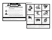
NOTE ON USE CAUTION RISK OF ELECTRIC SHOCK DO NOT OPEN CAUTION: TO REDUCE THE RISK OF ELECTRIC SHOCK, DO NOT REMOVE COVER (OR BACK). NO USER-SERVICEABLE PARTS INSIDE. REFER SERVICING TO QUALIFIED SERVICE PERSONNEL. The lightning flash with arrowhead symbol, within an equilateral triangle, is intended to alert the user to the presence of uninsulated “dangerous voltage” within the product’s enclosure that may be of sufficient magnitude to constitute a risk of electric shock to persons.
2 System setup menu page 8 ~11 page page page page page 41 41, 42 42, 43 43 43, 44 page page page page page page 36 36 36 37 37 38 page 38 page 38, 39 page page page page 39 39 40 40
Getting Started Getting Started Contents Getting Started Accessories ··············································································2 Before using·············································································2 Cautions on installation ·························································2 Cautions on handling······························································2 Preparing the remote control unit ········································2 Inserting the batteries ···
Getting Started Getting Started Thank you for choosing the DENON AVR-2106 A/V Surround Receiver. This remarkable component has been engineered to provide superb surround sound listening with home theater sources, such as DVD, as well as providing outstanding high fidelity reproduction of your favorite music sources. As this product is provided with an immense array of features, before you begin hookup and operation we recommend that you review the contents of this manual before proceeding.
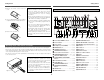
Getting Started Getting Started Inserting the batteries Part names and functions q Remove the remote control unit’s rear cover. w Set two R6P/AA batteries in the battery compartment in the indicated direction. e Put the rear cover back on. Notes on batteries: • Replace the batteries with new ones if the set does not operate even when the remote control unit is operated nearby the unit. (The included batteries are only for verifying operation.
Getting Started Remote control unit Easy Setup and Operation For details on the functions of these parts, refer to the pages given in parentheses ( ). Indicator··············(31, 33) • This section contains the basic steps necessary to configure the AVR-2106 according to your listening room environment and the source equipment and loudspeakers you are using. • For optimum performance, we recommend using the Auto Setup function.
Easy Setup and Operation Easy Setup and Operation Speaker system layout Speaker connections • Connect the speaker terminals with the speakers making sure that like polarities are matched (< with <, > with >). Mismatching of polarities will result in weak central sound, unclear orientation of the various instruments, and the stereo image being impaired.
Easy Setup and Operation Easy Setup and Operation 2 Connections 2 Bi-Amp connections When making connections, also refer to the operating instructions of the other components. Certain loudspeakers are equipped with two sets of input terminals, for bi-amplification. The AVR-2106 power amp assign mode allows you to power bi-amp-capable speakers with two amplifier channels ( page 40). Be sure to consult the owner’s manual of your bi-ampcapable speakers for further information before proceeding.
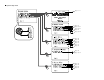
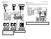
Easy Setup and Operation Easy Setup and Operation • For best picture quality (especially with progressive DVD and other high definition sources), choose the component video connection to your monitor TV. S-Video and composite video outputs are also provided if your TV does not have component video inputs. Connecting a DVD player and monitor TV • To connect the video output from the DVD player to the AVR-2106, you only need to choose one connection type.
Easy Setup and Operation POWER SPEAKER A Easy Setup and Operation ON/SOURCE SETUP MIC MODE 1 ENTER SETUP CURSOR ON/STANDBY SPEAKER Auto Setup The Auto Setup function of this unit performs an analysis of the speaker system to permit an appropriate automatic setting. 2 Measurement and setting details q: This sets the speaker connection, polarity, and bass reproduction ability. w: This sets the delay time from each speaker corresponding to the listening position.
Easy Setup and Operation Starting Auto Setup 1 Press the SETUP button. Easy Setup and Operation 4 Press the CURSOR D or H button to select “Start”, then press the CURSOR F button. • Start the measurements. • The “System Setup” menu appears. • Measurement is canceled if the MASTER VOLUME control knob is operated while the Auto Setup is performed.
Easy Setup and Operation Easy Setup and Operation Check of the measurement results About error messages • These error screens may be displayed when performing Auto Setup measurement and the automatic measurements can not be completed because of the speaker arrangement, measurement environment, or other factors. Please check the following matters, reset the pertinent items, and measure again. • When there is too much noise in the room, the speakers may not be detected properly.
Easy Setup and Operation 4 Press the CURSOR D or H button to select from the following three items based on the measurement results, then press the CURSOR F button. Store: Store the checked measurement values. All parameters are stored. Retry: Perform the measurement again. Measurement is repeated. Connecting Other Sources Cable indications The hookup diagrams on the subsequent pages assume the use of the following optional connection cables (not supplied).
Connecting Other Sources Connecting Other Sources The video conversion function On-screen display signals With the AVR-2106, the Video signal and the S-Video signal which were inputted are mutually converted. VIDEO signal input terminal (yellow) S-Video signal input terminal Video signal output to VIDEO MONITOR OUT terminal (yellow) Video signal output to S-Video MONITOR OUT terminal 1 E E C C 2 C E C C 3 E C C C 4 C C E C The flow of the video signals.
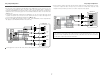
Connecting Other Sources Connecting Other Sources Connecting a TV/DBS tuner Connecting the external inputs (EXT. IN) terminals • For best picture quality choose the component video connection to your TV or DBS tuner. S-Video and composite video inputs are also provided if your TV or DBS tuner does not have component video output. • To connect the digital audio output from the TV or DBS tuner, you can choose from either the coaxial or optical connections.
Connecting Other Sources Connecting Other Sources Connecting a DVD recorder Connecting a VCR • If you wish to perform analog dubbing from a digital source, such as a DVD recorder to an analog recorder such as a cassette deck, you will need to connect the analog inputs and outputs as shown below, in addition to the digital audio connections. • The digital inputs and outputs connection is the same as that for a CD (MD) recorder.
Connecting Other Sources Connecting Other Sources Connecting a turntable Connecting the antenna terminals If humming or other noise is generated when the ground wire is connected, disconnect the ground wire. An FM antenna cable plug can be connected directly to the unit. Direction of broadcasting station Turntable (MM cartridge) AM loop antenna (Supplied) FM antenna 75 Ω/ohm COAXIAL cable A L AUDIO OUT R GND NOTE: • Do not connect two FM antennas simultaneously.
Connecting Other Sources Connecting the pre-out terminals • Use these terminals if you wish to connect external power amplifier(s) to increase the power of the front, center, surround and surround back sound channels, or for connection to powered loudspeakers. • When using only one surround back speaker, connect it to the left channel.
Basic Operation Playback using the external input (EXT. IN) terminals Basic Operation The signals being input to the external decoder input terminals are played without passing through the surround circuitry. Playback INPUT MODE FUNCTION ANALOG SURROUND MODE MASTER VOLUME Press the EXT. IN button to select the external input. FUNCTION SOURCE EXT.
Basic Operation Basic Operation Listening over headphones Connect the headphones to the PHONES jack. • The pre-out output (including the speaker output) is automatically turned off when headphones are connected. Checking the currently playing program source 2 On-screen display Press the ON SCREEN button. NOTE: • To prevent hearing loss, do not raise the volume level excessively when using headphones.
Basic Operation Basic Operation 2 Input mode display Surround • In the AUTO mode Depending on the input signal. STEREO/DIRECT/PURE DIRECT DIRECT/ PURE DIRECT • In the DIGITAL PCM mode • In the DIGITAL DTS mode STANDARD SELECT SURROUND PARAMETER 2 Input signal display Playing audio sources (CDs and DVDs) 2-channel playback modes • The AVR-2106 is equipped with 2-channel playback modes exclusively for music. • Select the mode to suit your tastes.
Basic Operation Basic Operation Dolby Pro Logic IIx (Pro Logic II) mode • To play in the PLIIx mode, set “S. BackSp” at the “Speaker Configuration” setting to “1sp” or “2sp”. • To play in the PL PLIIx mode, set “Surround Back” at the “Power Amp Assign” setting. 1 When the “SB CH OUT” parameter is set to “ON”. (Set “S. BACK” at system setup to “SMALL” or “LARGE”.) Display (Pro Logic IIx Music mode) • The Dolby Pro Logic II indicator lights.
Basic Operation Basic Operation 2 Surround parameters w FUNCTION INPUT MODE STANDARD SURROUND MODE FUNCTION ENTER SURROUND PARAMETER CURSOR STANDARD SELECT SURROUND PARAMETER SURROUND BACK INPUT MODE DTS NEO:6 mode 1 Press the STANDARD button to select the DTS NEO:6 mode. The mode switches as shown below each time the button is pressed. DOLBY PLIIx 2 3 4 5 DTS NEO:6 Play a program source. Press the SURROUND PARAMETER button to select the surround parameter mode.
Basic Operation 3 Basic Operation Press the STANDARD button to select the STANDARD (Dolby/DTS Surround) mode. When performing this operation from the main unit’s panel, press the SURROUND MODE button, then turn the SELECT knob and select Dolby Pro Logic IIx or DTS NEO:6. 4 Play a program source with the symbol. • The Dolby Digital indicator lights when playing Dolby Digital sources. • The DTS indicator lights when playing DTS sources.
Basic Operation Basic Operation 2 Dialog normalization FUNCTION INPUT MODE The dialog normalization function is activated automatically when playing Dolby Digital program sources. Dialog normalization is a basic function of Dolby Digital which automatically normalizes the dialog level (standard level) of the signals which are recorded at different levels for different program sources, such as DVD, DTV and other future formats that will use Dolby Digital.
Basic Operation 1 Basic Operation DENON original surround modes Select the input source. This unit is equipped with a high performance DSP (Digital Signal Processor) which uses digital signal processing to synthetically recreate the sound field. One of 7 preset surround modes can be selected according to the program source and the parameters can be adjusted according to the conditions in the listening room to achieve a more realistic, powerful sound.
Basic Operation Basic Operation TONE CONTROL SURROUND MODE When turned counterclockwise: DIRECT SURROUND MODE STEREO MONO MOVIE ROCK ARENA CH SELECT/ENTER SURROUND PARAMETER CURSOR SURROUND PARAMETER DSP surround simulation 2 To operate the surround mode and the surround parameters from the remote control unit 1 Select the surround mode for the input channel. 3 4 5 Press the SURROUND PARAMETER button, and press the CURSOR D or H button to select the various parameters.
Basic Operation Basic Operation Tone control setting Channel Level 2 Adjusting the sound quality (tone) The tone control function will not work in the PURE DIRECT or DIRECT mode. 1 Press the TONE CONTROL button. The tone switches as follows each time the TONE CONTROL button is pressed. BASS 2 You can adjust the channel level either according to the playback sources or to suit your taste, as described below. 1 Press the CH SELECT button to select the speaker whose level you want to adjust.
Basic Operation Basic Operation Listening to the radio FUNCTION BAND PRESET ON SCREEN Hold the PRESET • button and press the POWER switch on the main unit. • The unit automatically begins searching for FM broadcast stations. When the first FM broadcast station is found, that station is stored in the preset memory at channel A1. Subsequent stations are automatically stored in order at preset channels A1 to A8, B1 to B8, C1 to C8, D1 to D8, E1 to E8, F1 to F8 and G1 to G8 for a maximum of 56 stations.
Basic Operation 4 Press the TUNING (+) or (–) button to tune in the desired station. The frequency changes continuously when the button is held in. Basic Operation Checking the preset stations The preset (broadcast) stations can be checked on the on-screen display. Press the ON SCREEN button repeatedly until the “Tuner Preset Stations” screen appears on the OSD. PTY identifies the type of RDS program.
Basic Operation FUNCTION Basic Operation PRESET PTY 5 To continue searching, repeat step 4. If no station broadcasting the designated program type is found when all the frequencies have been searched, “NO PROGRAMME” is displayed. TUNER PRESET RDS RT RDS search PTY search Use this function to automatically tune to FM stations that provide the RDS service. 1 Set the input source to “TUNER”. (Main unit) 2 3 Use this function to find RDS stations broadcasting a designated program type (PTY).
Basic Operation RT (Radio Text) Advanced Operation “RT” appears on the display when radio text data is received. 1 2 Remote control unit Set the input source to “TUNER”. Press the RT button. While receiving an RDS broadcast station, the text data broadcast from the station is displayed. To turn the display off, press the RT button again. If no text data is being broadcast, “NO TEXT DATA” is displayed. Operating DENON audio components 1 Set the MODE 1 switch to “AUDIO”. MODE 2 MODE 1 2.
Advanced Operation OFF Advanced Operation ON SOURCE NUMBER MODE 1 • DENON and other makes of components can be operated by setting the preset memory. • This remote control unit can be used to operate components of other manufacturers without using the learning function by registering the manufacturer of the component as shown in the list of preset codes ( End of this manual). • Operation is not possible for some models. Set the MODE 1 switch to “AUDIO” or “VIDEO”.
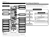
Advanced Operation 1. Digital video disc player (DVD) system buttons ON/SOURCE : Power on/standby OFF : DENON DVD power off 6, 7 : Manual search (forward and reverse) 2 : Stop 1 : Play 8, 9 : Auto search (to beginning of track) 3 : Pause 0 ~ 9, +10 : Number DISC SKIP + : Disc skip (for DVD changer only) DISPLAY : Switch display MENU : Menu RETURN : Return SETUP : Setup •, ª, 0, 1 : Cursor up, down, left and right ENTER : Enter setting Advanced Operation 2.
Advanced Operation Advanced Operation 4. Digital broadcast satellite (DBS) tuner and cable (CABLE) system buttons DVD/VDP POWER 5. Monitor TV (TV) system buttons TV POWER NUMBER MODE 1 MODE 2 Punch through “Punch Through” is a function allowing you to operate the PLAY, STOP, MANUAL SEARCH and AUTO SEARCH buttons on CD, TAPE, CDR/MD, DVD/VDP or VCR components when in the DBS/CABLE or TV mode. By default, nothing is set.
Advanced Operation Advanced Operation Initialization of the microprocessor FUNCTION REC SELECT If the indication on the display is not normal or if the operation of the unit is not correct, then the microprocessor should be reset by the following procedure. POWER SPEAKER Other functions Playing one source while recording another (REC OUT mode) 1 2 3 Press the REC SELECT button to display the “RECOUT SOURCE” on the display. Turn the FUNCTION knob to select the source you wish to record.
Advanced Setup – Part 1 On-screen display and front display Advanced Setup – Part 1 The AVR-2106 is equipped with an intuitive and easy-to-understand on-screen display, and is equipped with an alphanumeric front panel display that can also be used to check and adjust settings. We recommend that you use the on-screen display when you make system adjustments. Some representative front display and on-screen display examples are shown below.
Advanced Setup – Part 1 Advanced Setup – Part 1 Input Setup Setting the Input Function Level Setting the Digital In Assign. This setting assigns the digital input terminals of the AVR-2106 for the different input sources. 1 Press the CURSOR D or H button to select “Input Setup” at the “System Setup” menu, then press the ENTER button. • The “Input Setup” menu appears.
Advanced Setup – Part 1 Setting the Function Rename The names of the input sources displayed on the front display and the on-screen display can be changed. The names or brands of the devices connected to the input sources can be input. 1 Press the CURSOR D or H button to select “Function Rename” at the “Input Setup” menu, then press the ENTER button. Advanced Setup – Part 1 4 Repeat step 3 to complete input of the input source name.
Advanced Setup – Part 1 Setting the Auto Tuner Preset Use this to automatically search for FM broadcasts and store up to 56 stations at preset channels A1 to 8, B1 to 8, C1 to 8, D1 to 8, E1 to 8, F1 to 8 and G1 to 8. 1 Press the CURSOR D or H button to select “Auto Tuner Preset” at the “Input Setup” menu, then press the ENTER button. • The “Auto Tuner Preset” screen appears.
Advanced Setup – Part 1 3 4 Press the ENTER button to enter the setting. Advanced Setup – Part 1 Option Setup • The “Advanced Playback” menu appears. Setting the Muting Level Press the CURSOR D or H button to select “Exit”, then press the ENTER button. This sets the amount of attenuation applied for audio output muting. • The “System Setup” menu appears. 1 Press the CURSOR D or H button to select “Option Setup” at the “System Setup” menu, then press the ENTER button.
Advanced Setup – Part 1 Setting the Power Amp Assign. Advanced Setup – Part 1 Setting the Setup Lock Make this setting to switch the power amplifier for the surround back channel to Bi-Amp. The system setup settings can be locked so that they cannot be changed easily. 1 1 Press the CURSOR D or H button to select “Power Amp Assign.” at the “Option Setup” menu, then press the ENTER button. • The “Power Amp Assign.” screen appears.
Advanced Setup – Part 2 2 Parameters Advanced Setup – Part 2 This Speaker Setup section describes the procedures to make speaker settings manually (without using the Auto Setup function), as well as to make manual changes to settings that have already been made by the Auto Setup function. ENTER CURSOR The composition of the signals output to each channel and the frequency response are adjusted automatically according to the combination of speakers actually being used.
Advanced Setup – Part 2 1 Press the CURSOR D or H button to select “Delay Time” at the “Speaker Setup” menu, then press the ENTER button. • The “Delay Time” screen appears. Advanced Setup – Part 2 Setting the Channel Level • Use this setting to balance the playback levels in different channels and make them appear equal. • From the listening position, listen to the test tones produced from the speakers to adjust the level.
Advanced Setup – Part 2 Advanced Setup – Part 2 Setting the Crossover Frequency • To cancel the settings, press the CURSOR H button to select “Level Clear” on the “Channel Level” screen, then make the settings again. • When adjusting the level of an active subwoofer system, you may also need to adjust the subwoofer’s own volume control. • When you adjust the channel levels while in the system setup channel level mode, the channel level adjustments made will affect all surround modes.
Advanced Setup – Part 2 Advanced Setup – Part 2 2 Assignment of low frequency signal range 2 Subwoofer Mode The only signals produced from the subwoofer channel are LFE signals (during playback of Dolby Digital or DTS signals) and the low frequency signal range of channels set to “Small” in the setup menu. The low frequency signal range of channels set to “Large” are produced from those channels.
Advanced Setup – Part 2 Advanced Setup – Part 2 System setup items and default values (set upon shipment from the factory) 1. Auto Setup Auto Setup 1 Auto Setup Power Amp Assign. Set this to switch the surround back channel’s power amplifier for Bi-amp use. Default setting Page SURROUND BACK 8 ~ 11 2. Speaker Setup Speaker Setup 1 Speaker Config.
Advanced Setup – Part 2 Advanced Setup – Part 2 4. Advanced Playback Advanced Playback Default setting Page 0 ms 38 1 Audio Delay Sets the audio delay to delay the sound and synchronize it with the picture. Auto 2 Surround Mode Sets the Auto surround mode function. Auto Surround Mode = ON 38, 39 Option Setup 5. Option Setup Default setting Page 1 Muting Level This sets the amount of attenuation for audio output muting.
Troubleshooting Symptom Troubleshooting If a problem should arise, first check the following. 1. Are the connections correct? 2. Have you operated the receiver according to the operating instructions? 3. Are the speakers, turntable and other components operating properly? If this unit is not operating properly, check the items listed in the table below. Should the problem persist, there may be a malfunction. Disconnect the power immediately and contact your store of purchase.
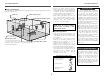
Additional Information Surround back speakers Additional Information • Other types of audio: These signals are designed to recreate a 360° sound field using three to five speakers. Optimum surround sound for different sources There are currently various types of multi-channel signals (signals or formats with more than two channels).
Additional Information With this set, speaker(s) for 1 or 2 channels are required to achieve a 6.1-channel system (DTS-ES, etc.). Adding these speakers, however, increases the surround effect not only with sources recorded in 6.1 channels but also with conventional 2- to 5.1-channel sources. Furthermore, all the DENON original surround modes ( page 24) are compatible with 7.1-channel playback, so you can enjoy 7.1-channel sound with any signal source.
Additional Information Additional Information [2] When not using surround back speakers Front speakers Center speaker Surround The AVR-2106 is equipped with a digital signal processing circuit that lets you play program sources in the surround mode to achieve the same sense of presence as in a movie theater. 2 Dolby Digital compatible media and playback methods Symbol indicating Dolby Digital compatibility: The following are general examples. Also refer to the player’s operating instructions.
Additional Information • Whereas with conventional Dolby Pro Logic the surround channel playback frequency band was limited, Dolby Pro Logic II offers a wider band range (20 Hz to 20 kHz or greater). In addition, the surround channels were monaural (the surround left and right channels were the same) with previous Dolby Pro Logic, but with Dolby Pro Logic II they are played as stereo signals.
Additional Information [3] DTS-ES Extended Surround™ DTS-ES Extended Surround is a new multi-channel digital signal format developed by Digital Theater Systems Inc. While offering high compatibility with the conventional DTS Digital Surround format, DTS-ES Extended Surround greatly improves the 360degree surround impression and space expression thanks to further expanded surround signals. This format has been used professionally in movie theaters since 1999. In addition to the 5.
Additional Information Additional Information Surround modes and parameters Signals and adjustability in the different modes When playing Dolby Digital and DTS signals Channel output Mode DIRECT / PURE DIRECT STEREO EXTERNAL INPUT DOLBY PRO LOGIC II DOLBY PRO LOGIC IIx DTS NEO:6 DOLBY DIGITAL DTS SURROUND 5CH/7CH STEREO ROCK ARENA JAZZ CLUB VIDEO GAME MONO MOVIE MATRIX VIRTUAL FRONT L/R CENTER SURROUND L/R SURROUND BACK L/R SUBWOOFER C C C C C C C C C C C C C C C E E B B B B B B B B B B B B E E
Specifications 2 Video section Specifications • Standard video terminals Input / output level and impedance: 1 Vp-p, 75 Ω/ohms Frequency response: 5 Hz ~ 10 MHz — +1, –3 dB • S-Video terminals Input / output level and impedance: Y (brightness) signal — 1 Vp-p, 75 Ω/ohms C (color) signal — 0.3 Vp-p, 75 Ω/ohms Frequency response: 5 Hz ~ 10 MHz — +1, –3 dB • Color component video terminal Input / output level and impedance: Y (brightness) signal — 1 Vp-p, 75 Ω/ohms PB/CB (blue) signal — 0.
2 List of preset codes Audio Dynamic 005, 085 014, *[111] Audiovox 088 Aiwa 009 Beaumark 087 Jensen 013, 026 Hitachi 010 Broksonic 086, 093 JVC 004, 005, 006, 026, 029, 043, 044, 045, 006, 011 Calix 088 Konka 012, 013 Candle 006, 087, 088, 089, 090 Magnavox 005 Canon 049, 057 Mitsubishi 004 Capehart 025, 055, 056, 071 Kodak 088 Panasonic 014 Carver 015 Lloyd 009, 094 Philips 005, 015, 016, 017 CCE 095 LXI 088 Pioneer 003, 008 Citizen 006, 007, 087, 088, 089,
Optonica 021 Sylvania 009, 015, 016, 017, 041, 049, 094 Bauer 155 Panasonic 024, 049, 064, 066, 067, 068, 069, 107 Symphonic 009, 094 Belcor 047 Perdio 009 Tandy 009 Bell & Howell 045, 118 Pentax 009, 013, 023, 058, 090 Tashiko 009, 088 Bradford 061 Philco 015, 016, 049 Tatung 004, 026, 030 Brockwood 003, 047 Philips 015, 021, 042, 049, 105 Teac 004, 009, 026, 094 Candle Pilot 088 Technics 024, 049 Pioneer 005, 013, 029, 036, 037, 038, 045, 085 Teknika 009, 010, 022
Futuretech 004 Minutz 066 SBR 015 GE 020, 036, 037, 040, 044, 058, 066, 088, Mitsubishi 001, 016, 039, 048, 056, 057, 058, 065, Schneider 015 081, 082, 083, 105 Scott 062 000, 015, 029, 031, 039, 048, 051, 056, Montgomery Ward 011, 020, 144, 145, 146 Sears 008, 014, 021, 022, 023, 024, 025, 040, 057, 067, 068, 069, 116 Motorola 121, 147 Grundy 062 MTC 031, 034, 039, 048, 095 Hitachi 029, 031, 051, 052, 070, 111, 112, 113, NAD 008, 075, 076, 128 119, 120, 125, 147 Goldstar 052
CABLE DBS (SATELLITE) Emerson 004, 005, 006, 007 003, 008, 009, 010 ABC 006, *[007], 008, 009 Alphastar 054 Fisher Archer 010, 011 Chaparral 035, 036 JVC 018, 019 011, 012, 013, 014, 017 006, 015, 035 Century 011 Dishnet 053 Kenwood Citizen 011 Drake 037, 038 Magnavox Colour Voice 012, 013 Echostar Dish 062, 066 Marantz 016, 028, 035 Comtronic 014 GE 048, 055, 056 MCS 016, 024 Eastern 015 General Instruments 039, 040, 041 Onkyo 025, 027 Garrard 011 Grundig 070,
Magnavox 002 Marantz 002 Onkyo 016, 018 DVD preset codes Optimus 007, 008 Panasonic 012 B Model No. Philips 002 Pioneer 007, 008, 009 Sony 013, 014, 015 Technics 012 Victor 004 Wards 007 Yamaha 010, 011 *[ ] : Preset codes set upon shipment from the factory.
TOKYO, JAPAN www.denon.com Denon Brand Company, D&M Holdings Inc.