AV SURROUND RECEIVER AVR-3805 OPERATING INSTRUCTIONS BEDIENUNGSANLEITUNG MODE D’EMPLOI ISTRUZIONI PER L’USO INSTRUCCIONES DE OPERACION GEBRUIKSAANWIJZING BRUKSANVISNING CH SEL ENTER RC-970 FOR ENGLISH READERS FÜR DEUTSCHE LESER POUR LES LECTEURS FRANCAIS PER IL LETTORE ITALIANO PARA LECTORES DE ESPAÑOL VOOR NEDERLANDSTALIGE LEZERS FOR SVENSKA LÄSARE PAGE SEITE PAGE PAGINA PAGINA PAGINA SIDA 112 164 125 186 247 308 369 ~ ~ ~ ~ ~ ~ ~ PAGE SEITE PAGE PAGINA PAGINA PAGINA SIDA 163 124 185 246 307 368
ENGLISH DEUTSCH FRANCAIS ITALIANO ESPAÑOL NEDERLANDS CAUTION SVENSKA NOTE ON USE / HINWEISE ZUM GEBRAUCH / OBSERVATIONS RELATIVES A L’UTILISATION / NOTE SULL’USO NOTAS SOBRE EL USO / ALVORENS TE GEBRUIKEN / OBSERVERA RISK OF ELECTRIC SHOCK DO NOT OPEN CAUTION: TO REDUCE THE RISK OF ELECTRIC SHOCK, DO NOT REMOVE COVER (OR BACK). NO USER SERVICEABLE PARTS INSIDE. REFER SERVICING TO QUALIFIED SERVICE PERSONNEL.
ENGLISH 2 2 We greatly appreciate your purchase of the AVR-3805. To be sure you take maximum advantage of all the features the AVR-3805 has to offer, read these instructions carefully and use the set properly. Be sure to keep this manual for future reference, should any questions or problems arise. “SERIAL NO. PLEASE RECORD UNIT SERIAL NUMBER ATTACHED TO THE REAR OF THE CABINET FOR FUTURE REFERENCE” 2 INTRODUCTION Thank you for choosing the DENON AVR-3805 Digital A / V Surround Receiver.
ENGLISH 4 FEATURES 1. Dolby Digital Using advanced digital processing algorithms, Dolby Digital provides up to 5.1 channels of widerange, high fidelity surround sound. Dolby Digital is the default digital audio delivery system for DVD and North American DTV. 8.
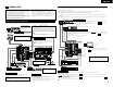
ENGLISH 5 CONNECTIONS Connecting the video components • Do not plug in the AC cord until all connections have been completed. • Be sure to connect the left and right channels properly (left with left, right with right). • Insert the plugs securely. Incomplete connections will result in the generation of noise. • Use the AC OUTLET for audio equipment only. Do not use them for hair driers, etc.
ENGLISH Connecting the video components equipped with S-Video jacks • When making connections, also refer to the operating instructions of the other components. • A note on the S input jacks The input selectors for the S inputs and Video inputs work in conjunction with each other. • The AVR-3805 is equipped with a function for converting video signals. • The signal connected to the S-Video signal terminal is output to the composite video and component video monitor out terminals.
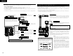
ENGLISH Connecting the antenna terminals DIRECTION OF BROADCASTING STATION 75 Ω/ohms COAXIAL CABLE Connecting the MULTI ZONE jacks AM loop antenna assembly AM LOOP ANTENNA (Supplied) Connect to the AM antenna terminals. 1 2 3 For instructions on operations using the MULTI ZONE FUNCTIONS.
ENGLISH [3] ZONE2/ZONE3 SPEAKER OUT and PREOUT CONNECTIONS • If another power amplifier or pre-main (integrated) amplifier is connected, the ZONE2/ZONE3 output terminals can be used to play a different program source in ZONE2/ZONE3 the same time. • ZONE2/ZONE3 SPEAKER OUT can be used when “ZONE2/ZONE3” is selected at System Setup Menu “Power Amp Assign”. In this case, Surround Back Speaker OUT cannot be used for MAIN ZONE.
ENGLISH Connections • When making connections, also refer to the operating instructions of the other components. Speaker system connections • Connect the speaker terminals with the speakers making sure that like polarities are matched (≈ with ≈, √ with √ ). Mismatching of polarities will result in weak central sound, unclear orientation of the various instruments, and the sense of direction of the stereo being impaired.
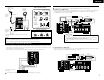
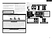
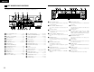
ENGLISH 6 PART NAMES AND FUNCTIONS Display !5 !4 !3 Front Panel !2 !1!0 o i u y !6 • For details on the functions of these parts, refer to the pages given in parentheses ( ). @8 #2#1 #0 @9 @7 @6 @5 @4 !2œ!3œ!4œ!5œ!6œ!7 œ!8œ!9œ@0@1@2@3 q w q CH SEL ENTER #3 w q w q w e r t y u i o !0 !1 !2 !3 !4 !5 !6 10 t u o e r y i œ!0 Power ON/STANDBY switch..........................(36) Power switch ...........................................(36, 54) Headphone jack (PHONES) ......................
ENGLISH 7 SETTING UP THE SYSTEM Remote control unit • For details on the functions of these parts, refer to the pages given in parentheses ( ). Remote control signal transmitter ................................(30) • Once all connections with other AV components have been completed as described in “CONNECTIONS” (see pages 5 to 9), make the various settings described below on the monitor screen using the AVR-3805’s on-screen display function.
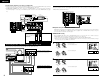
ENGLISH 2. Speaker Setup 4. Advanced Playback Speaker Setup 1 2 Speaker Configuration Delay Time Advanced Playback Default settings Input the combination of speakers in your system and their corresponding sizes (SMALL for regular speakers, LARGE for full-size, full-range) to automatically set the composition of the signals output from the speakers and the frequency response.
ENGLISH • Speaker system layout Basic system layout • The following is an example of the basic layout for a system consisting of eight speaker systems and a television monitor: Subwoofer Before setting up the system 1 Check that all the connections are correct, then turn on the main unit’s power. Setup will not be possible when the unit is set to Pure Direct ON, the Video Off mode, or when the headphones are plugged in. Therefore, please cancel the mode or reverse the condition.
ENGLISH 1 1 CH SEL ENTER (Remote control unit) 2 4 Setting the Auto Setup / Room EQ CH SEL ENTER Select “Auto Setup / Room EQ” at the System Setup Menu. CH SEL ENTER (Remote control unit) CH SEL ENTER (Remote control unit) (Main unit) Setup w Press the CURSOR left button. CH SEL ENTER 5 (Main unit) CH SEL ENTER (Main unit) Start the measurements. Measurement of each channel is performed as follows.
ENGLISH About the error message These error screens will be displayed when performing the measurements of Auto Setup / Room EQ and the automatic measurements can not be completed because of the speaker arrangement, measurement environment, or other factors. Please check the following matters, reset the pertinent items, and measure again. When there is too much noise in the room, the speakers may not be detected properly.
ENGLISH 1-2 Setting the Manual EQ Setup 1-3 Setting the Room EQ Setup Adjust the tone of the various speakers except subwoofer speaker while listening to the sound (music). Select the setting of an Equalizer that has been set with Auto Setup or Manual EQ. 1 1 CH SEL ENTER (Remote control unit) 2 (Main unit) Select “Manual EQ Setup” at the Auto Setup / Room EQ Menu.
ENGLISH NOTES: • The Equalizer setting of Normal, Flat and Front can be selected after performing the Auto Setup. • When the speaker set as “None” with the Auto Setup is change to on manually, the equalizer of “Normal”, “Front” and “Flat” cannot be used. • The Equalizer setting can be selected directly by ROOM EQ button in Main unit or Remote control unit. • When headphone is connected, the Room EQ cannot be used.
ENGLISH 3 (Remote control unit) 4 2-1 Setting the type of speakers Select the Equalizer curve. CH SEL ENTER CH SEL ENTER • The composition of the signals output to each channels and the frequency response are adjusted automatically according to the combination of speakers actually being used. (Main unit) 5 Dislay the parameter screen. Select the speaker channel.
ENGLISH • Parameters Large.................Select this when using speakers that have sufficient performance for reproducing bass sound below the frequency set for the Crossover Frequency mode. Small .................Select this when using speakers that do not have sufficient performance for reproducing bass sound below the frequency set for the Crossover Frequency mode. When this is set, bass sound with a frequency below the frequency set for the Crossover Frequency mode is sent to the subwoofer. None…… ...
ENGLISH 2-3 Setting the Channel Level • • • • Use this setting to adjust so that the playback level between the different channels is equal. From the listening position, listen to the test tones produced from the speakers to adjust the level. The level can also be adjusted directly from the remote control unit. (For details, see page 41.) When both surround speakers A and B are used, their playback levels can be adjusted separately.
ENGLISH When you adjust the channel levels while in the SYSTEM SETUP CHANNEL LEVEL mode, the channel level adjustments made will affect all surround modes. Consider this mode a Master Channel Level adjustment mode. After you have completed the SYSTEM SETUP CHANNEL LEVEL adjustments, you can then activate the individual surround modes and adjust channel levels that will be remembered for each of those modes.
ENGLISH NOTES: — Assignment of low frequency signal range (2-1) — • The only signals produced from the subwoofer channel are LFE signals (during playback of Dolby Digital or DTS signals) and the low frequency signal range of channels set to “SMALL” in the setup menu. The low frequency signal range of channels set to “LARGE” are produced from those channels.
ENGLISH 3-1 Setting the Digital In Assignment 3-2 Setting the Ext. In Subwoofer Level • This setting assigns the digital input jacks of the AVR-3805 for the different input sources. • Set the method of playback of the analog input signal connected to the Ext.In Subwoofer. 1 1 CH SEL ENTER (Remote control unit) 2 (Main unit) At the Input Setup Menu select “Digital In Assign”. *Input Setup Digital In Display the Digital Inputs screen.
ENGLISH 3 AUTO: When there are multiple input signals, the input signals are detected and the input signal to be output from the video monitor output terminal is selected automatically in the following order: component video, S-Video, composite video. Component: The signal connected to the component video terminal is always played. Video conversion is not conducted, so no image is output from the monitor output terminal when there is no input signal to the component terminal.
ENGLISH 3 4 CH SEL ENTER CH SEL ENTER (Remote control unit) (Main unit) CH SEL ENTER (Remote control unit) 4 1 Enter the setting. The Input Setup Menu reappears. 4-2 Setting the Dolby Digital Setup Sets the down-mixing method when not using a center speaker or surround speakers. OFF: The dynamic range is not compressed. ON: The dynamic range is compressed automatically according to the combination of speakers being used.
ENGLISH 4-3 Setting the Auto Surround Mode The surround mode used at last for the three types of input signals shown below is stored in the memory, and the signal is automatically played with that surround mode the next time it is input. Note that the surround mode setting is also stored separately for the different input sources.
ENGLISH 4 CH SEL ENTER (Remote control unit) CH SEL ENTER 5-3, 5-4 Setting the Trigger Out Setup Enter the setting. The Option Setup Menu reappear. • Set the Trigger Out output 1 for the different input sources. (Main unit) 1 CH SEL ENTER CH SEL ENTER 5-2 Setting the Zone2 Vol. Level (Remote control unit) Set the Zone2 pre-out output level adjustment. 1 CH SEL ENTER (Remote control unit) 2 CH SEL ENTER (Remote control unit) 4 (Main unit) 2 At the Option Setup Menu select “Zone2 Vol.
ENGLISH 5-5 Setting the Muting Level 5-6 Setting the On Screen Display (OSD) • This sets the amount of attenuation at audio output muting. 1 CH SEL ENTER (Remote control unit) 2 CH SEL ENTER (Main unit) Select “Muting Level” at the Option Setup Menu. *Option Setup Muting Level • Use this to turn the on-screen display (messages other than the menu screens) on or off. • Sets the on-screen display’s display mode. Mode 1: Prevents flickering of the on-screen display when there is no video signal.
ENGLISH 5-7 Protecting the setting After completing system setup The system setup settings can be locked so that they cannot be changed easily. This button can be pressed at any time during the system setup process to complete the process. 1 1 CH SEL ENTER (Remote control unit) 2 Press the SYSTEM SETUP button at the System Setup Menu. The changed settings are entered and the on-screen display turns off.
ENGLISH 8 REMOTE CONTROL UNIT Operating DENON audio components • The included remote control unit (RC-970) can be used to operate not only the AVR-3805 but other remote control compatible DENON components as well. In addition, the memory contains the control signals for other remote control units, so it can be used to operate non-DENON remote control compatible products.
ENGLISH 4. Tuner system buttons 2. TAPE deck (TAPE) system buttons Preset memory The included remote control unit can be used to operate devices of different brands by registering the preset number corresponding to the brand of your device. For some models the remote control unit or the device may not operate properly. In this case, use the learning function (page 33) to store your device’s remote control signals in the included remote control unit.
ENGLISH 3. Video deck (VCR-1/VCR-2) system buttons Operating a component stored in the preset memory 1 4. Monitor TV (TV),digital broadcast satellite (DBS) tuner and cable (CABLE) system buttons Press the mode selector button for the component you want to operate. 1 NOTE: • For the DVD player remote control buttons, function names may differ according to manufacturer. Compare with the remote control operation of the various components. 2 2.
ENGLISH Learning function System call If your AV component is not a DENON product or if it cannot be operated using the preset memory, it can be controlled with the accessorious remote control unit by storing its remote control signals in the remote control unit. For some remote control signals it is not possible to “learn” the signals or the device will not operate properly. In such cases use the remote control unit included with the device to operate it.
ENGLISH NOTES: • The remote control signals of the buttons pressed while registering the system call signals are emitted, so be careful not to operate the components accidentally (cover the remote sensors, for example). • If you exceed the number of signals that can be registered, There will be a changeover to the System Call registration screen. Setting the back light’s lighting time 1 Press the power ON button and the OFF button at the same time. 2 Press the “5” button to select Light setup.
ENGLISH (2) Resetting “learned” buttons (4) Resetting the punch through setting 1 Press the power ON button and the OFF button at the same time. 1 Press the power ON button and the OFF button at the same time. 2 Press the “6” button to select resetting. 2 Press the “6” button to select resetting. 4 3 Press the “2” button to resetting the “learned” buttons 3 Press the “4” button to resetting the “punch through”setting. 2, 3 4 The mode buttons will all light.
ENGLISH 9 OPERATION Playing the input source 1 Operating the remote control unit 5 1 1 Select“AMP”using the AMP/TUNER button. 2 [SOURCE MENU] • Operate the source. 3 3 [SURROUND MENU] • Operate the surround mode. 3 1 3 2 5 1 1 2 3 1 Before operating (Remote control unit) 1 Refer to “CONNECTIONS” (pages 5 to 9) and check that all connections are correct. 2 Select “AMP” using the AMP/TUNER button.
ENGLISH Note on playing a source encoded with DTS • Noise may be generated at the beginning of playback and while searching during DTS playback in the AUTO mode. If so, play in the DTS mode. 3 Select the play mode. Example: Stereo Input mode display Playback using the external input (EXT. IN) jacks Depending on the input signal. • In the AUTO mode 1 Set the external input (EXT. IN) mode. Press the EXT. IN to switch the external input.
ENGLISH Playing audio sources (CDs and DVDs) After starting playback The AVR-3805 is equipped with three 2-channel playback modes exclusively for music. Select the mode to suit your tastes. [1] Adjusting the sound quality (TONE) The tone control function will not work in the PURE DIRECT and the DIRECT mode. 1 1 PURE DIRECT mode In this mode, the music is played with an extremely high level of sound quality.
ENGLISH [4] Combining the currently playing sound with the desired image 1 Simulcast playback Use this switch to monitor a video source other than the audio source. Press the VIDEO SELECT button, turn the FUNCTION knob until the desired source appears on the display. [6] Switching the surround speakers 1 1 1 1 1 The surround speakers switch as shown below each time the SPEAKER button is pressed.
ENGLISH 10 MULTI ZONE Multi-zone playback with multi-source MULTI ZONE MUSIC ENTERTAINMENT SYSTEM • When the outputs of the “ZONE2 (ZONE3)” OUT terminals are wired and connected to integrated amplifiers installed in other rooms, different sources can be played in rooms other than the main zone in which this unit and the playback devices are installed. (Refer to ZONE2 (ZONE3) on the diagram below.) • MULTI ZONE SPEAKER OUT can be used when “ZONE3” is selected at System Setup Menu “Power Amp Assign”.
ENGLISH [1] Outputting a program source to an amplifier, etc., in a different room (ZONE2, ZONE3 mode) 1 11 SURROUND 3 Press the “ON” button. Before playing with the surround function • Before playing with the surround function, be sure to use the test tones to adjust the playback level from the different speakers. This adjustment can be performed with the system setup (see page 20) or from the remote control unit, as described below.
ENGLISH Fader function • This function makes it possible to lower the volume of the front channels (FL, C and FR) or the rear channels (SL, SR, SBL and SBR) together. Use it for example to adjust the balance of the sound from each position when multi-channel music sources are played. 1 2 3 Select “FADER”. CH SEL ENTER Play a program source with the mark. • For operating instructions, refer to the manuals of the respective components. Set the surround parameter mode.
ENGLISH 6 Set the various surround parameters. CH SEL ENTER (Remote control unit) 7 If the setting ends, press the “ENTER” or “SURROUND PARAMETER” button. DTS NEO:6 mode • Surround playback can be performed for the analog input and PCM digital input 2-channel signals. CH SEL ENTER (Main unit) NOTE: • There are four Dolby Surround Pro Logic modes (NORMAL, PHANTOM, WIDE and 3 STEREO).
ENGLISH NOTE: • When “Default” is selected and the CURSOR left button is pressed, “MODE” and “TONE” are automatically reset to the default values and “CINEMA EQ” is set to “OFF”. 3 Play a program source with the mark. Surround parameters w Light DTS NEO:6 Mode: • Cinema This mode is optimum for playing movies. Decoding is performed with emphasis on separation performance to achieve the same atmosphere with 2-channel sources as with 6.1-channel sources.
ENGLISH NOTE: • When “Default” is selected and the CURSOR left button is pressed, “CINEMA EQ.” and “D.COMP.” are automatically turned off, “LFE” is reset, and the tone is set to the default value. Checking the input signal The input signal can be checked by pressing the remote control unit’s ON SCREEN button. (See page 24.) SIGNAL: fs: FORMAT: OFFSET: FLAG: (Remote control unit) Displays the type of signal (DTS, DOLBY DIGITAL, PCM, etc.). Displays the input signal’s sampling frequency.
ENGLISH Adjusting the Audio Delay When watching a DVD or other video source, the picture on the monitor may seem delayed with respect to the sound. In this case, adjust the audio delay to delay the sound and synchronize it with the picture. The audio delay setting is stored separately for each input source. 1 4 Press the ENTER button and display the Advanced Playback Menu. 8 CH SEL ENTER Enter the setting. The Advanced Playback Menu reappears. CH SEL ENTER 1 q Select the input source.
ENGLISH 12 DSP SURROUND SIMULATION • The AVR-3805 is equipped with a high performance DSP (Digital Signal Processor) which uses digital signal processing to synthetically recreate the sound field. One of ten preset surround modes can be selected according to the program source and the parameters can be adjusted according to the conditions in the listening room to achieve a more realistic, powerful sound.
ENGLISH NOTES: • The surround speaker setting can also be changed with the SPEAKER button on the remote control unit. • When “Default” is selected and the CURSOR left button is pressed, “CINEMA EQ.” and “D.COMP.” are automatically turned off, “ROOM SIZE” is set to “medium”, “EFFECT LEVEL” to “10”, “DELAY TIME” to “30ms” and “LFE” to “0dB”. • The “ROOM SIZE” expresses the expansion effect for the different surround modes in terms of the size of the sound field, not the actual size of the listening room.
ENGLISH 2 Surround modes and parameters Signals and adjustability in the different modes Signals and adjustability in the different modes Channel output SURROUND SURROUND SUBL/R BACK L/R WOOFER Parameter (default values are shown in parentheses) When playing Dolby Digital signals When playing DTS signals When playing PCM signals When playing ANALOG signals When playing DSD signals When playing DVDAUDIO signals When playing Dolby Digital and DTS signals Mode D.
ENGLISH 13 LISTENING TO THE RADIO Signals and adjustability in the different modes SURROUND PARAMETER • Check that the remote control unit is set to AMP or TUNER. PRO LOGIC II / II x ONLY NEO:6 MUSIC EXT.
ENGLISH Preset memory 1 Recalling preset stations • Recalling preset stations from the remote control unit. • Preset stations can be chosen directry preset channel and channel range button. (see page 31.) Use the “Auto tuning” or “Manual tuning” operation to tune in the station to be preset in the memory. 2 1 Press the MEMORY button. Watching the display, press the SHIFT button to select the preset memory block.
ENGLISH RDS (Radio Data System) RDS search RDS (works only on the FM band) is a broadcasting service which allows station to send additional information along with the regular radio program signal. The following three types of RDS information can be received on this unit: Use this function to automatically tune to FM stations that provide RDS service. 1 2 Program Type (PTY) Set the input function to “TUNER”. PTY identifies the type of RDS program.
ENGLISH PTY search TP search Use this function to find RDS stations broadcasting a designated program type (PTY). For a description of each program type, refer to “Program Type (PTY)”. 1 Use this function to find RDS stations broadcasting traffic program (TP stations). 1 Set the input function to “TUNER”. Set the input function to “TUNER”. (Remote control unit) (Remote control unit) (Main unit) (Main unit) 1 1 2 Press the RDS button until “PTY SEARCH” appears on the display.
ENGLISH 16 TROUBLESHOOTING RT (Radio Text) “RT” appears on the display when radio text data is received. When the RDS button is pressed until “RT” appears on the display while receiving an RDS broadcast station, the text data broadcast from the station is displayed. To turn the display off, use the left and right cursor buttons on the remote control unit. If no text data is being broadcast, “NO TEXT DATA” is displayed. “left” “right” If a problem should arise,first check the following table. 1.
ENGLISH Remote control unit Symptom Cause Measures • Batteries dead. • Remote control unit too far from this unit. This unit does not operate • Obstacle between this unit and properly when remote control remote control unit. unit is used. • Different button is being pressed. • < and > ends of battery inserted in reverse. Page • Replace with new batteries. • Move closer. 30 30 • Remove obstacle. 30 • Press the proper button. • Insert batteries properly.
ENGLISH (3) When using different surround speakers for movies and music To achieve more effective surround sound for both movies and music, use different sets of surround speakers and different surround modes for the two types of sources. Speaker setting examples Here we describe a number of speaker settings for different purposes. Use these examples as guides to set up your system according to the type of speakers used and the main usage purpose. Front speakers Center speaker 1.
ENGLISH Surround The AVR-3805 is equipped with a digital signal processing circuit that lets you play program sources in the surround mode to achieve the same sense of presence as in a movie theater. Dolby Surround (1) Dolby Digital Dolby Digital is the multi-channel digital signal format developed by Dolby Laboratories. Dolby Digital consists of up to “5.
ENGLISH DTS-ES Extended Surround TM DTS Digital Surround Digital Theater Surround (also called simply DTS) is a multi-channel digital signal format developed by Digital Theater Systems. DTS offers the same “5.1” playback channels as Dolby Digital (front left, front right and center, surround left and surround right) as well as the stereo 2-channel mode.
ENGLISH DTS 96/24 The sampling frequency, number of bits and number of channels used for recording of music, etc., in studios has been increasing in recent years, and there are a growing number of high quality signal sources, including 96 kHz/24 bit 5.1-channel sources. For example, there are high picture/sound quality DVD video sources with 96 kHz/24 bit stereo PCM audio tracks.
ENGLISH 2. Speaker Setup 4. Advanced Playback Speaker Setup 1 2 Speaker Configuration Delay Time Advanced Playback Default settings Input the combination of speakers in your system and their corresponding sizes (SMALL for regular speakers, LARGE for full-size, full-range) to automatically set the composition of the signals output from the speakers and the frequency response.
ENGLISH Surround modes and parameters Signals and adjustability in the different modes Channel output Mode FRONT L/R CENTER SURROUND SURROUND SUBL/R BACK L/R WOOFER When playing Dolby Digital signals When playing DTS signals When playing PCM signals Signals and adjustability in the different modes When playing ANALOG signals When playing DSD signals When playing DVDAUDIO signals DIRECT / PURE DIRECT C E E E B C C C C C C MULTI CH DIRECT C B B B B E E E E C C STEREO C E
ENGLISH Relationship between the video input signal and monitor output according to the VIDEO INPUT MODE settings Signals and adjustability in the different modes SURROUND PARAMETER PRO LOGIC II / II x ONLY SUBWOOFER PANORAMA DIMENSION ON/OFF NEO:6 MUSIC EXT.IN CENTER WIDTH CENTER IMAGE SW ATT E E E E E E E E E E E E E E E E E E C E E E E C (3) C (3) E E C (3) C (3) E E E E E C (0.
ENGLISH 18 SPECIFICATIONS 2 Audio section • Power amplifier Rated output: Dynamic power: Output terminals: • Analog Input sensitivity / input impedance: Frequency response: S/N: Distortion: Rated output: • Digital D/A output: Front: 120 W + 120 W (8 160 W + 160 W (6 Center: 120 W (8 160 W (6 Surround: 120 W + 120 W (8 160 W + 160 W (6 Surround back: 120 W + 120 W (8 160 W + 160 W (6 140 W x 2 ch (8 Ω/ohms) 210 W x 2 ch (4 Ω/ohms) 240 W x 2 ch (2 Ω/ohms) Front, Center, Surr.
16-11, YUSHIMA 3-CHOME, BUNKYO-KU, TOKYO 113-0034, JAPAN Telephone: (03) 3837-5321 Printed in Japan 511 4158 005