AV SURROUND RECEIVER AVR-3806 OPERATING INSTRUCTIONS
SAFETY INSTRUCTIONS 2 SAFETY PRECAUTIONS CAUTION RISK OF ELECTRIC SHOCK DO NOT OPEN CAUTION: TO REDUCE THE RISK OF ELECTRIC SHOCK, DO NOT REMOVE COVER (OR BACK). NO USER-SERVICEABLE PARTS INSIDE. REFER SERVICING TO QUALIFIED SERVICE PERSONNEL.
2 NOTE ON USE / OBSERVATIONS RELATIVES A L’UTILISATION • Avoid high temperatures. Allow for sufficient heat dispersion when installed in a rack. • Eviter des températures élevées. Tenir compte d’une dispersion de chaleur suffisante lors de l’installation sur une étagère. • Keep the apparatus free from moisture, water, and dust. • Protéger l’appareil contre l’humidité, l’eau et la poussière. • Unplug the power cord when not using the apparatus for long periods of time.
Getting Started Getting Started Thank you for choosing the DENON AVR-3806 Digital Surround A / V amplifier. This remarkable component has been engineered to provide superb surround sound listening with home theater sources such as DVD, as well as providing outstanding high fidelity reproduction of your favorite music sources. As this product is provided with an immense array of features, we recommend that before you begin hookup and operation that you review the contents of this manual before proceeding.
2 System setup menu page 9~13 page 80 page 80 page 80 page 81 page 75 page 76 page 76, 77 page 77, 78 page 78, 79 page 79 page 69 page 63 page 70 page 63, 64 page 70 page 64 page 70, 71 page 64 page 65, 66 page 72 page 66, 67 page 72, 73 page 67 page 73, 74 page 67 page 74 page 67, 68 page 68 page 68, 69
2 We greatly appreciate your purchase of the AVR-3806. 2 To be sure you take maximum advantage of all the features the AVR-3806 has to offer, read these instructions carefully and use the set properly. Be sure to keep this manual for future reference should any questions or problems arise. “SERIAL NO.
Getting Started Getting Started Advanced Setup – Part 1 Navigating through the System Setup Menu····················61 On screen display and front display ···································62 Audio Input Setup Setting the Digital In Assignment·········································63 Setting the DENON LINK ·····················································63 Setting the EXT.
Getting Started Getting Started Cautions on installation Noise or disturbance of the picture may be generated if this unit or any other electronic equipment using microprocessors is used near a tuner or TV. If this happens, take the following steps: • Install this unit as far away as possible from the tuner or TV. • Run the antenna wires from the tuner or TV away from this unit’s power supply cord and input/output connection cables.
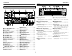
Getting Started Getting Started Part names and functions Display !4 !3 !2 Front panel !1 !0 o iu y For details on the functions of these parts, refer to the pages given in parentheses ( ). !4 @0 !3 !9 !2 !1 !0 q w !5 !6 !7 !8 #8 #7# #5 # #00 @9 @8 @ #66 #5 #44 #3 #2 # #11 # @77 q Input signal indicator The respective indicator will light corresponding to the input signal.
Getting Started Getting Started Rear panel Remote control unit For details on the functions of these parts, refer to the pages given in parentheses ( ).
Easy Setup and Operation Speaker system layout Easy Setup and Operation 2 Basic system layout • This section contains the basic steps necessary to configure the AVR-3806 according to your listening room environment and the source equipment and loudspeakers you are using. • For optimum performance, we recommend using the Auto Setup function. • If you wish, you can set the various settings manually without using Auto Setup ( page 75 ~ 79).
Easy Setup and Operation Easy Setup and Operation 2 Connections Speaker connections • Connect the speaker terminals with the speakers making sure that like polarities are matched (< with <, > with >). Mismatching of polarities will result in weak central sound, unclear orientation of the various instruments, and the stereo image being impaired.
Easy Setup and Operation Easy Setup and Operation For best picture quality (especially with progressive DVD and other high definition sources), choose the component video or HDMI connection to your monitor TV. S-Video and composite video outputs are also provided if your TV does not have component video inputs. Connecting a DVD player and monitor TV • To connect the video output from the DVD player to the AVR-3806, you only need to choose one connection type.
Easy Setup and Operation Easy Setup and Operation Auto Setup / Room EQ The Auto Setup and Room EQ function of this unit performs an analysis of the speaker system and measures the acoustic characteristics of your room to permit an appropriate automatic setting. The AVR-3806’s Audyssey MultEQ XT function has the feature that it provides the optimum listening environment at all listening positions in the home theater, where there are often multiple listeners viewing programs together.
Easy Setup and Operation Easy Setup and Operation Connecting a microphone POWER ENTER SETUP MIC 1 Connect the microphone for Auto Setup to the SETUP MIC jack on the front panel of the unit. Turning on the power 1 Turn on your subwoofer. Set the volume to halfway and set the crossover frequency to the maximum or Low pass filter off if your subwoofer can adjust the output volume and the crossover frequency Some subwoofers have a standby mode.
Easy Setup and Operation Starting Auto Setup 1 2 Press the SETUP button. • The “System Setup Menu” appears. Press the CURSOR D or H button to select the “Auto Setup / Room EQ”, then press the ENTER button. Easy Setup and Operation Power Amp Assign Preliminary measurements The AVR-3806 has available surround back amplifier channel. If no surround back speakers are used in the main room, their amplifier channels can be assigned for multi-zone use or the front speaker‘s Bi-Amp connection.
Easy Setup and Operation 3 Check the results of the speaker detection, then press the ENTER button. • The second screen appears. [ Second screen ] 4 If the check ends, press the ENTER button again. NOTE: • If the results are not as expected or if an error message is displayed, select “Retry” and perform the measurements again. (For details on the error messages ( page 13).
Easy Setup and Operation 3 4 If the check ends, press the ENTER button again. Press the CURSOR D or H button to select whether or not to save the data you have checked. Easy Setup and Operation About the error message These error messages will be displayed when performing the measurements of Auto Setup and the automatic measurements can not be completed because of the speaker arrangement, measurement environment, or other factors.
Connecting Other Sources Connecting Other Sources NOTE: • Do not plug in the power supply cord until all connections have been completed. • When making connections, also refer to the operating instructions of the other components. • Be sure to connect the left and right channels properly (left with left, right with right). • Note that binding pin-plug cables together with power supply cords or placing them near a power transformer will result in hum or other noise.
Connecting Other Sources Connecting Other Sources The video conversion function The AVR-3806 is equipped with a function for up and down converting video signals. Because of this, the AVR-3806’s MONITOR OUT terminal can be connected to the monitor (TV) with a set of cables offering a higher quality connection, regardless of how the player and the AVR-3806’s video input terminals are connected.
Connecting Other Sources Connecting Other Sources Connecting equipment with HDMI (High-Definition Multimedia Interface) terminals [To convert analog video signals to HDMI signals] Connecting a TV tuner • For best picture quality choose the component video connection to your TV. S-Video and composite video outputs are also provided if your TV does not have component video inputs. • To connect the digital audio output from the TV, you can choose from either the coaxial or the optical connections.
Connecting Other Sources Connecting Other Sources Connecting a DBS tuner Connecting the external inputs (EXT. IN) terminals • These terminals are for inputting multi-channel audio signals from an outboard decoder, or a component with a different type of multi-channel decoder, such as a DVD Audio player, or a multichannel Super Audio CD player, or other future multi-channel sound format decoder. • The video signal connection is the same as that for a DVD player ( page 8).
Connecting Other Sources Connecting Other Sources Connecting a DVD recorder Connecting a VCR • There are two sets of video deck (VCR) terminals, so two video decks can be connected for simultaneous recording or video copying. • For best picture quality choose the component video connection to your DVD recorder. S-Video and composite video outputs are also provided. If you choose to use the component video connection, it needs to be assigned.
Connecting Other Sources Connecting Other Sources Connecting a CD player Connecting a CD recorder or MD recorder To connect the digital audio output from the CD player, you can choose from either the coaxial or optical connections. If you choose to use the optical connection, it needs to be assigned. For more information about Digital Input Assignment ( page 63).
Connecting Other Sources Connecting Other Sources Connecting equipment with HDMI (High-Definition Multimedia Interface) terminals DENON LINK connections • High quality digital sound with reduced digital signal transfer loss can be enjoyed by connecting a separately sold DENON LINK compatible DVD player.
Connecting Other Sources Connecting Other Sources NOTE: • The audio signals on the multi/stereo area of Super Audio CDs are not output. If the Super Audio CD is a hybrid CD, only the audio signals in the CD area are output. • Use a compatible player to play DVD Audio discs that are copyright protected by CPPM. • Among the devices that support HDMI, some devices can control other devices via the HDMI connector; however, the AVR-3806 cannot be controlled by another device via the HDMI connector.
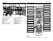
Connecting Other Sources Connecting Other Sources 2 AM loop antenna assembly Connecting the antenna terminals An F-type FM antenna cable plug can be connected directly. 1 2 Connect to the AM antenna terminals. 3 FM ANTENNA DIRECTION OF BROADCASTING STATION Connection of AM antennas 1. Push the lever. AM LOOP ANTENNA (Supplied) Remove the vinyl tie and take out the connection line. 75 Ω/ohms COAXIAL CABLE Bend in the reverse direction. 4 a. With the antenna on top any stable surface. 2.
Connecting Other Sources Connecting Other Sources Connecting the CONTROL terminal Connecting the XM terminal • AVR-3806 is the XM Ready® receiver. You can receive XM Satellite Radio® by connecting to the XM Connect-and-PlayTM (sold separately) and subscribing the XM service. • Plug the XM Connect-and-Play antenna into XM terminal on the rear panel. • Position the XM Connect-and-Play antenna near a south-facing window to receive the best signal. For details, see “XM Satellite Radio” ( page 45).
Connecting Other Sources Connecting Other Sources Connecting the MULTI ZONE terminals ZONE2 / ZONE3 speaker out connections For instructions on operations using the MULTI ZONE functions ( • When the surround back’s power amplifier is assigned to the ZONE2 or ZONE3 output channel at “Power Amp Assign” in the “System Setup Menu”, the surround back speaker terminals can be used as the ZONE2 or ZONE3 speaker out terminals ( page 57).
Connecting Other Sources Connecting Other Sources Connecting the pre-out terminals Connecting the power supply cord • Use these terminals if you wish to connect external power amplifier(s) to increase the power of the front, center, surround and surround back sound channels, or for connection to powered loudspeakers. • When using only one surround back speaker, connect it to the left channel.
Basic Operation 2 ZONE3 mode Basic Operation To operate the ZONE3 function. Playback Operating the remote control unit The RC-1024 remote control has a backlit EL display whose contents change according to the mode or function selected, with the appropriate remote commands for that mode or function. The EL display switches as shown below with respect to the selected mode. 2 AMP mode To operate the MAIN ZONE function.
Basic Operation Basic Operation Playing the input source VIDEO SELECT FUNCTION 2 To choose the surround sound mode STANDARD VOLUME 1 Select the input source to be played. Example: Dolby Digital Press the STANDARD button. Example: CD For more information about the surround modes ( 33, 34). (Main unit) SOURCE PHONES EXT.
Basic Operation Basic Operation Playback using the external input (EXT. IN) terminals Press the EXT. IN button on the main unit or INPUT MODE button on the remote control unit to switch the external input. When operating the remote control unit: (Remote control unit) The mode switches as shown below each time the INPUT MODE button is pressed: AUTO EXT.IN PCM DTS ANALOG • Cancelling the external input mode: Press the INPUT MODE or ANALOG button to switch to the desired input mode ( page 29, 30).
Basic Operation Basic Operation DIMMER ROOM EQ Checking the currently playing program source, etc. Press the INPUT MODE button. 2 On screen display Press the ON SCREEN button. INPUT MODE Each time an operation is performed, a description of that operation appears on the display connected to AVR-3806’s VIDEO MONITOR OUT terminal. Also, the unit’s operating status can be checked during playback. Such information as the position of the input selector and the surround settings is output in sequence.
Basic Operation Basic Operation 2 Selecting the analog mode 2 Input signal display Room EQ function • DOLBY DIGITAL Press the ANALOG button on the main unit or INPUT MODE button on the remote control unit to switch to the analog input. • DTS ANALOG (exclusive analog audio signal playback mode): The signals input to the analog input terminals are decoded and played.
Basic Operation Basic Operation Sources recorded in stereo Sources recorded in monaural Surround Playing modes for different sources The AVR-3806 is equipped with many surround modes. We recommend using the surround modes as described below in order to achieve the maximum effect for the specific signal source. is a 6.1-channel/7.1-channel surround Dolby Digital or DTS Surround (5.
Basic Operation Basic Operation Playing audio sources (CDs and DVDs) 2-channel playback modes PURE DIRECT DIRECT/STEREO • The AVR-3806 is equipped with three 2-channel playback modes exclusively for music. • Select the mode to suit your tastes. 2 STEREO mode Use this mode to adjust the tone and achieve the desired sound. Press the DIRECT/STEREO button to select the STEREO mode. 2 PURE DIRECT mode This mode reproduces the sound with extremely high quality.
Basic Operation STANDARD Basic Operation SURROUND ENTER PARAMETER Dolby Digital mode and DTS Surround (only with digital input) 1 2 NIGHT CURSOR SURROUND BACK Press the STANDARD button to select the “STANDARD (Dolby/DTS Surround)” mode. Play a program source with the , mark. • The Dolby Digital indicator lights when playing Dolby Digital sources. • The DTS indicator lights when playing DTS sources. light light Press the SURROUND BACK button. Lights when the Surround Back CH is on.
Basic Operation Basic Operation 2 Dialogue Normalization 2 Checking the input signal The dialogue normalization function is activated automatically when playing Dolby Digital program sources. Dialogue normalization is a basic function of Dolby Digital which automatically normalizes the dialog level (standard level) of the signals which are recorded at different levels for different program sources, such as DVD, DTV and other future formats that will use Dolby Digital.
Basic Operation 2 Surround parameters q CINEMA EQ. (Cinema Equalizer): The Cinema EQ function gently decreases the level of the extreme high frequencies, compensating for overly-bright sounding motion picture soundtracks. Select this function if the sound from the front speakers is too bright. This function only works in the Dolby Pro LogicIIx, Dolby Pro Logic, Dolby Digital, DTS Surround, DTS NEO:6 and WIDE SCREEN modes. D.COMP.
Basic Operation STANDARD Basic Operation SURROUND ENTER PARAMETER Dolby Pro LogicIIx (Pro LogicII) mode • To play in the PLIIx mode, set “Sp.Back” at the Speaker Configuration setting to “1spkr” or “2spkrs”. • To play in the PLIIx mode, set “Surround Back” at the Power Amp Assign setting. 1 When the “SB CH OUT” parameter is set to “OFF”. (Set “Sp.Back” at the System Setup to “None”). Display Press the STANDARD button to select the “Dolby Pro LogicIIx” mode.
Basic Operation STANDARD Basic Operation SURROUND ENTER PARAMETER 6 Press the CURSOR F or G button to adjust the parameters setting. DEFAULT setting: Press the CURSOR F button to select “Default Yes 0”, then parameters set to default setting. CURSOR USER MODE 7 Press the ENTER or SURROUND PARAMETER button to complete the setting. USER MODE STANDARD • There are four Dolby Surround Pro Logic modes (NORMAL, PHANTOM, WIDE and 3 STEREO).
Basic Operation Basic Operation DTS NEO:6 mode Surround playback can be performed for the analog input and digital input 2-channel signals. 1 Press the STANDARD button to select the “DTS NEO:6” mode. The mode switches as shown below each time the STANDARD button is pressed. DOLBY PLIIx 2 3 DTS NEO:6 Play a program source. Press the SURROUND PARAMETER button. • The surround parameter menu is displayed. 5 6 7 Press the CURSOR D or H button to select the various surround parameters.
Basic Operation Basic Operation DENON original surround modes The AVR-3806 is equipped with a high performance DSP (Digital Signal Processor) which uses digital signal processing to synthetically recreate the sound field. One of ten preset surround modes can be selected according to the program source and the parameters can be adjusted according to the conditions in the listening room to achieve a more realistic, powerful sound.
Basic Operation 7CH STEREO Basic Operation SURROUND ENTER PARAMETER DSP surround simulation 1 Select the surround mode for the input channel. Example: DSP surround simulation mode (Remote control unit) Example: 7CH STEREO mode 3 4 5 Press the CURSOR D or H button to select the various surround parameters. Press the CURSOR F or G button to adjust the parameter settings. Press the ENTER or SURROUND PARAMETER button to complete the setting.
Basic Operation Basic Operation 2 Surround parameters r ENTER EFFECT: This parameter turns the effect signals with multi surround mode speaker effects on and off in the WIDE SCREEN mode. When this parameter is turned off, the SBL and SBR channel signals are equivalent to the SL and SR channels, respectively. SURROUND PARAMETER • Use the tone control setting to adjust the bass and treble as desired. • The tone control function will not work in the PURE DIRECT or DIRECT mode.
Basic Operation 4 Press the CURSOR G button to select the “Tone Defeat OFF”. Basic Operation Channel level You can adjust the channel level either according to the playback sources or to suit your tastes, as described below. 1 5 6 Fader function Press the ENTER button. • The “Channel Vol.” screen is displayed. 1 2 Press the CURSOR D or H button to select the “Bass” or “Treble”. Press the CURSOR F or G button to set the level.
Basic Operation Basic Operation Listening to the radio Manual tuning Check that the remote control unit is set to AMP or TUNER. 1 Auto tuning Set the input source to “TUNER”. FUNCTION 1 Set the input source to “TUNER”. (Main unit) (Remote control unit in the AMP mode) (Main unit) 2 TUNING PRESET 3 TUNER Press the TUNER button on the remote control unit to select the TUNER mode. (Remote control unit) Watching the display, press the BAND button to select the desired band (AM, FM or XM).
Basic Operation Basic Operation Preset memory 1 2 3 4 Checking the preset stations Use the “Auto tuning” or “Manual tuning” operation to tune in the station to be preset in the memory. Press the TUNER button on the remote control unit to select the TUNER mode. Press the ON SCREEN button (in the AMP mode) repeatedly until the “Tuner Preset Stations” screen appears on the OSD. (Remote control unit) Press the MEMORY button. Press the MEMORY BLOCK (A to G) button.
Basic Operation Basic Operation Checking the XM signal strength and Radio ID XM Satellite Radio AVR-3806 is the XM Ready® receiver. You can receive XM Satellite Radio® by connecting to the XM separately) and subscribing the XM service. Connect-and-PlayTM (sold 2 Introducing XM Satellite Radio FUNCTION ENTER STATUS There’s a world of audio listening pleasure beyond AM and FM. XM Satellite Radio. Select from over 150 channels of music, news, sports, comedy, talk, and entertainment.
Basic Operation Basic Operation Channel selection 1 2 3 Direct access of channels Set the input source to “TUNER”. Press the TUNER button on the remote control unit to select the TUNER mode. Set the input source to “TUNER”. Watching the display, press the BAND button to select the XM mode. 1 2 Press the SEARCH button in the XM mode. Press the NUMBER buttons to enter the desired channel. For example, if you want to access channel 123 (ex.XM123) press the Number buttons as shown below.
Advanced Operation Advanced Operation Select “ZONE3” mode. Remote control unit Example: Select “AMP” mode. MODE SELECTOR Select “SYSTEM CALL” mode. Select “ZONE2” mode. AMP/LAST 2 Operating DENON audio components 1 Operate the audio component. For details, refer to the component’s operating instructions. It may not be possible to operate some models. Press the MODE SELECTOR buttons to select the component you want to operate. • The icon for the selected mode flashes.
Advanced Operation 1. CD player (CD), CD recorder (CDR) system buttons 6, 7 2 1 8, 9 3 0 ~ 9, +10 : : : : : : Manual search (forward and reverse) Stop Play Auto search (to beginning of track) Pause Number Default setting = CD The preset codes of a CDR can be recorded in the CD mode so that the CD recorder can be operated ( page 49). It is only possible to set the preset memory for either the CD or CDR. To operate a DENON CDR player, preset “30626” or “31868”.
Advanced Operation Advanced Operation IR segment 3 MODE SELECTOR Referring to the included List of Preset Codes ( End of this manual), press the NUMBER to input the preset code (a 5-digit number) for the manufacturer of the component whose signals you want to store in the memory. •The top IR segment blinks once after each key press. •If the remote recognizes the manufacturer’s code, the IR segment blinks twice. You have 10 seconds to press each digit.
Advanced Operation 1. DVD player (DVD), DVD recorder (DVDR) system buttons Advanced Operation 2. Satellite (SAT) tuner, cable (CABLE) system buttons 6, 7 2 1 8, 9 3 : : : : : Manual search (forward and reverse) Stop Play Auto search (cue) Pause Default setting = SAT The preset codes of a CABLE can be recorded in the SAT/CBL mode so that the cable device can be operated ( page 49). It is only possible to set the preset memory for either the SAT or CBL.
Advanced Operation Advanced Operation 3. Video deck (VCR) system buttons 4. Monitor TV (TV), system buttons When there are codes usable for the preset device, those codes are sent when the buttons below are pressed. If not, by default the DVD codes are punched through. If the punch through setting is made after the preset memory is set, the codes are sent with priority.
Advanced Operation Advanced Operation IR segment 4 MODE SELECTOR Press the button that you wish to be learned. • The display will go off and the unit will enter the learning standby mode. If a button that cannot be “learned” is pressed, the IR segment lights and the learning setup mode is cancelled. The AMP/LAST button cannot be “learned”. SYSTEM CALL 5 Point the remote control units directly at each other and press and hold in the button on the other remote control unit which you want to “learn”.
Advanced Operation Advanced Operation IR segment 2 Press the 9, 7, 8 button (9 → 7→ 8) to select system call setting. 3 4 Press the SYSTEM CALL button (1 to 3) you want to register the system call. MODE SELECTOR SYSTEM CALL ON NUMBER SETUP System call The accessorius remote control unit is equipped with “system call” function allowing a series of remote control signals to be transmitted by pressing a single button.
Advanced Operation Punch through Buttons used in the CD, DVD, and VCR modes can be assigned to the buttons which are not normally used in the TV and SAT/CBL modes. For example, when the DVD mode is set to the punch through mode in the TV mode, the DVD mode’s PLAY (1), STOP (2), MANUAL SEARCH (6, 7), AUTO SEARCH (8, 9) and PAUSE (3) button’s signals are sent in the TV mode. — ( ) 1 Press and hole hold the the SET SETUP UP button for at least three seconds. • The IR segment blinks twice.
Advanced Operation Advanced Operation IR segment MODE SELECTOR 2 Resetting all learned buttons 2 Resetting the punch through setting 1 Press and hole hold the the SET SETUP UP button for at least three seconds. andMODE hole the SET UP button button(TV for or atSAT least/ Press the SELECTOR three seconds. CBL) you want to reset. 2 3 → 7→68)). to select a the 9,9,7,7,6 button 8 button (9→ 7→ Press the (9 → • The IR segment blinks twice. setting.
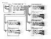
Advanced Operation Advanced Operation Multi zone music entertainment system • When the outputs of the “ZONE2 (ZONE3)” OUT terminals are wired and connected to power amplifiers installed in other rooms, different sources can be played in rooms other than the MAIN ZONE in which this unit and the playback devices are installed. (Refer to ZONE2 (ZONE3) on the diagram below.
Advanced Operation Advanced Operation Multi-zone playback using the SPEAKER terminals 2 When using the SURROUND BACK amplifier as the ZONE2/ZONE3 output • When the surround back’s power amplifier is assigned to the ZONE2 or ZONE3 output channel at “Power Amp Assign” in the “System Setup Menu”, the surround back speaker terminals can be used as the ZONE2 or ZONE3 speaker out terminals ( page 72).
Advanced Operation Advanced Operation Outputting a program source to amplifier, etc., in a ZONE2 room (ZONE2 SELECT mode) FUNCTION 1 Press the ZONE2/3/REC SELECT button to display the “ZONE2 SOURCE” on the display. • The MULTI indicator lights. The display switches as follows each time the button is pressed. ZONE2/3/REC SERECT ZONE2 ON/OFF 2 With “ZONE2 SOURCE” displayed, turn the FUNCTION knob to select the source you want to output appears on the display.
Advanced Operation Advanced Operation Other function FUNCTION POWER SURROUND MODE Playing Super Audio CDs with DENON LINK 1 Select the input source to which DENON LINK was assigned at the “Digital In Assign” ( page 63) in the system setup. Example: DVD (Main unit) NIGHT PURE DIRECT ZONE2/3/REC SERECT When playing DSD signals in the DIRECT or PURE DIRECT mode, the DSD signals are converted into analog signals.
Advanced Operation Advanced Operation Multi-source recording / playback 2 Playing one source while recording another (REC OUT mode) 1 2 Press the ZONE2/3/REC SELECT button until “ZONE2 SOURCE” appears on the display. With “ZONE2 SOURCE” displayed, turn the FUNCTION knob until “RECOUT SOURCE” appears on the display. Last function memory • This unit is equipped with a last function memory which stores the input and output setting conditions as they were immediately before the power is switched off.
Advanced Setup – Part 1 Advanced Setup – Part 1 You can customize a variety of system setup so that it may be fitting for your listening environment. For the contents of a system menu and the initial setting of this unit ( page 82 ~ 84). Navigating through the System Setup Menu You can change setting using the buttons on the front panel or remote control unit. 1 2 CURSORD CURSORF ENTER SYSTEM SETUP CURSORH CURSORG Press the AMP button on the remote control unit.
Advanced Setup – Part 1 Advanced Setup – Part 1 Main menu On screen display and front display Main menu The AVR-3806 is equipped with an intuitive and easy-to-understand on screen display, and is equipped with an alpha-numeric front panel display tube that can also be used to check and adjust settings. We recommend that you use the on screen display when you make system adjustments. Some representative front panel and on screen display examples are shown below. *Audio In Setup Digital In No.
Advanced Setup – Part 1 Advanced Setup – Part 1 Audio Input Setup 2 Make the audio-related settings. Setting the Digital In Assignment This setting assigns the digital input terminals of the AVR-3806 for the different input sources. 1 Press the CURSOR D or H button to select “Audio Input Setup” at the “System Setup Menu”, then press the ENTER button. • The “Audio Input Setup” menu screen appears.
Advanced Setup – Part 1 SW Level: Sets the playback level of the analog signal that was input to the EXT. IN subwoofer terminal. Select according to the specifications of the player being used. Also refer to the player’s operating instructions. +15dB (default) recommended. (0, +5, +10 and +15 can be selected.) 3 Advanced Setup – Part 1 Setting the Function Rename The names of the input sources displayed on the front display and on the on screen display can be changed.
Advanced Setup – Part 1 Tuner Presets 2 Auto Preset Memory Use this to automatically search for FM broadcasts and store up to 56 stations at preset channels A1 to 8, B1 to 8, C1 to 8, D1 to 8, E1 to 8, F1 to 8 and G1 to 8. 1 Advanced Setup – Part 1 2 Preset Skip When selecting preset channels pressing the PRESET button, it is possible to skip specific preset channels. 1 Press the CURSOR D or H button to select the “Tuner Presets” at the “Audio Input Setup” menu, then press the ENTER button.
Advanced Setup – Part 1 4 Repeat step 3 to input the preset channel name. Advanced Setup – Part 1 9 Press the CURSOR D or H button to select “Exit”, then press the ENTER button. • The “System Setup Menu” reappears. If you wish to set the preset channel name back to as it was initially, press the CURSOR H button with the preset channel name highlighted. If the same digital input terminal is selected, the setting for the input source that was previously assigned switches to “OFF”.