AV SURROUND RECEIVER AVR-4806 OPERATING INSTRUCTIONS
SAFETY PRECAUTIONS FCC INFORMATION (For US customers) 1. PRODUCT This product complies with Part 15 of the FCC Rules. Operation is subject to the following two conditions: (1) this product may not cause harmful interference, and (2) this product must accept any interference received, including interference that may cause undesired operation. CAUTION RISK OF ELECTRIC SHOCK DO NOT OPEN 2.
2 System Setup Menu CH SEL ENTER CH SEL ENTER CH SEL ENTER CH SEL ENTER CH SEL ENTER CH SEL ENTER CH SEL ENTER 3 page page page page page 19~25 122 123 123, 124 124, 125 page page page page page page page 113, 114 114, 115 115, 116 116~118 118, 119 119, 120 120, 121 page page page page page page page 89, 90 90 91 91, 92 92 93 93~95 page page page page page page 96, 97 97 97, 98 98, 99 99 100 page page page page 101 102 102 103, 104 page page page page page page page 105 106, 107 108 109 1
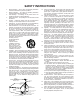
SAFETY INSTRUCTIONS 1. 2. 3. 4. 5. 6. 7. 8. 9. 10. 11. 12. Read Instructions – All the safety and operating instructions should be read before the product is operated. Retain Instructions – The safety and operating instructions should be retained for future reference. Heed Warnings – All warnings on the product and in the operating instructions should be adhered to. Follow Instructions – All operating and use instructions should be followed.
Getting Started Thank you for choosing the DENON AVR-4806 Digital Surround A / V receiver. This remarkable component has been engineered to provide superb surround sound listening with home theater sources such as DVD, as well as providing outstanding high fidelity reproduction of your favorite music sources. As this product is provided with an immense array of features, we recommend that before you begin hookup and operation that you review the contents of this manual before proceeding.
Getting Started Listening to the radio Video Setup Auto tuning...................................................................................65 Manual tuning ..............................................................................65 Preset memory ............................................................................66 Checking the preset stations .......................................................66 Recalling preset stations ........................................................
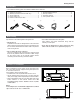
Getting Started Accessories • Check that the following parts are included in addition to the main unit: q w e r t y u i o Operating instructions ..................................................1 Warranty (for North America model only).....................1 Service station list.........................................................1 Power supply cord ........................................................1 Remote control unit (RC-995) .......................................
Getting Started Cautions on handling • Whenever the power switch is in the STANDBY state, the apparatus is still connected on AC line voltage. Please be sure to turn off the power switch or unplug the cord when you leave home for, say, a vacation. • Switching the input function when input terminals are not connected. A clicking noise may be produced if the input function is switched when nothing is connected to the input terminals.
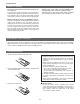
Getting Started Operating range of the remote control unit • Point the remote control unit at the remote sensor on the main unit as shown on the diagram. • The remote control unit can be used from a straight distance of approximately 23 feet/7 meters from the main unit, but this distance will be shorter if there are obstacles in the way or if the remote control unit is not pointed directly at the remote sensor.
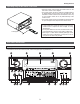
Getting Started #7 #6 #5 #4 #3 #2 #1 #0 @9 @8 @7 @6 @0 @1 @2 @3 @4 @5 q Power ON/STANDBY switch ................................(21) w Power indicator ........................................................(21) e Power switch ......................................................(21, 86) r Headphones jack (PHONES) .................................(44) t V.AUX INPUT terminals .........................................(30) y SETUP MIC jack ........................................................
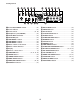
Getting Started Display !7 !6 !5 !4 !3 q w !2 !1 !0 o i y r t e q Input signal indicator u !0 Recording output source indicator The respective indicator will light corresponding to the input signal. REC OUT mode is selected in ZONE3/REC SELECT. !1 DENON LINK indicator w Input signal channel indicator This lights during playback in a DENON LINK connection. The channels included in the input source will light. This lights when the digital signal is inputted.
Getting Started Remote control unit • For details on the functions of these parts, refer to the pages given in parentheses ( ). Remote control signal transmitter ............................................................(9) Power buttons.............................(21) System buttons ..........................(83) Mode selector buttons ...................................................(42, 70) Input source button ...................................................
Easy Setup and Operation • This section contains the basic steps necessary to configure the AVR-4806 according to your listening room environment and the source equipment and loudspeakers you are using. • For optimum performance, we recommend using the Auto Setup function. • If you wish, you can set the various settings manually without using Auto Setup ( page 113 ~ 121). Easy to setup flow Placing the speakers. Auto setup flow Connecting a microphone. Connecting the speakers. Preliminary measurement.
Easy Setup and Operation Speaker system layout 2 Basic system layout (For a THX Ultra2 system) • The following is an example of the basic layout for a system consisting of eight speaker systems and a television monitor: Subwoofer Center speaker system Surround back speaker systems Front speaker systems Set these at the sides of the TV or screen with their front surfaces as flush with the front of the screen as possible.
Easy Setup and Operation Speaker connections • Connect the speaker terminals with the speakers making sure that like polarities are matched ( < with <, > with > ). Mismatching of polarities will result in weak central sound, unclear orientation of the various instruments, and the sense of direction of the stereo being impaired.
Easy Setup and Operation 2 Connections • The AVR-4806 can be configured for 10 speaker playback using two pairs of surround speakers (A+B) and one pair of surround back speakers as shown below. • The output of each power amplifier can be assigned to any desired channel to best suit the application. For details, refer to “Setting the Channel Setup” and “Setting the Power Amplifier Assignment” ( page 105 ~ 107). • When making connections, also refer to the operating instructions of the other components.
Easy Setup and Operation Connecting a DVD player and Monitor TV • To connect the video output from the DVD player to the AVR-4806, you only need to choose one connection type. Component video connection offers the best quality (and is required for progressive DVD playback), followed by S-Video, while composite video offers the lowest picture quality of the three connection types. For more information about the video up conversion function ( page 27).
Easy Setup and Operation • For best picture quality (especially with progressive DVD and other high definition sources) choose the component video connection to your monitor TV. S-Video and composite video outputs are also provided if your TV does not have component video inputs.
Easy Setup and Operation Auto Setup / Room EQ The Auto Setup and Room EQ function of this unit performs an analysis of the speaker system and measures the acoustic characteristics of your room to permit an appropriate automatic setting. The AVR-4806’s Audyssey MultEQ XT function has the feature that it provides the optimum listening environment at all listening positions in the home theater, where there are often multiple listeners viewing programs together.
Easy Setup and Operation ON POWER ENTER SETUP MIC AMP ENTER CURSOR ON/STANDBY SETUP CURSOR SETUP Connecting a microphone 1 When placing the microphone, adjust the height so that the microphone’s sound receptor is at the height of the ears of the listener. Be sure that at the beginning, the measurement is started with the microphone set up at the main listening position. It is not possible to measure properly if there are any obstacles between the speakers and microphone.
Easy Setup and Operation Turning on the power 1 Turn on your subwoofer. 2 3 Turn on your monitor (TV). Starting Auto Setup Set the volume to halfway and set the crossover frequency to the maximum or Low pass filter off if your subwoofer can adjust the output volume and the crossover frequency. Some subwoofers have a standby mode. Be sure to turn this function off before performing the Auto Setup procedure. Press the POWER switch. 1 Press the SETUP button.
Easy Setup and Operation Extra Setup Preliminary measurements • The AVR-4806 has seven available amplifier channels, some of which can be assigned for powering speakers in ZONE2 and ZONE3, depending on the speaker system complement in the main room. If this functionality is not needed, skip this “Extra Setup” procedure and proceed to “Preliminary Measurements” ( page 22, 23).
Easy Setup and Operation NOTE: • If the results are not as expected or if an error message is displayed, select “Retry” and perform the measurements again. (For details on the error messages ( page 25).) If the results of remeasurement are still not as expected or if an error message is displayed, turn off the power switch and check the speaker connections. Then start the measurements again from the beginning. • Measurement is cancelled when MASTER VOLUME is operated while the Auto Setup is performed.
Easy Setup and Operation Check of the measurement result 5 • The results of the measured items can be checked. 1 Press the CURSOR D or H button to select the items, then press the ENTER button. • Switch to the verification screen. • When measurements have been made using the measurement microphone, speakers with a built-in filter such as subwoofers might be set with a value that differs from the physical distance because of the internal electrical delay. [ First screen ] Press the ENTER button.
Easy Setup and Operation About the error message • These error messages will be displayed when performing the measurements of Auto Setup and the automatic measurements can not be completed because of the speaker arrangement, measurement environment, or other factors. Please check the following matters, reset the pertinent items, and measure again. Be sure to turn off the AVR-4806’s power before checking the speaker connections.
Connecting Other Sources Cable indications • The hookup diagrams on the subsequent pages assume the use of the following optional connection cables (not supplied).
Connecting Other Souces 2 The analog video to HDMI conversion function: The video conversion function • The AVR-4806’s video up-conversion function lets you output analog video input signals (component – 480i/576i, 480p/576p, 1080i or 720p; S-Video and composite video 480i/576i) to the HDMI monitor output terminal with the original resolution. • The on screen display signals are output from the HDMI monitor output terminal with a resolution of 480i/576i.
Connecting Other Souces Connecting equipment with HDMI (High-Definition Multimedia Interface) terminals [To convert analog video signals to HDMI signals] • The AVR-4806 is equipped with a function for converting analog video signals into HDMI signals. You can do this by either a component or a video or a S-Video connection. • Audio signals are not output from the HDMI monitor output terminal, so also make analog or digital audio connections.
Connecting Other Souces Connecting a TV tuner • For best picture quality choose the component video connection to your TV. S-Video and composite video outputs are also provided if your TV does not have component video inputs. • To connect the digital audio output from the TV, you can choose from either the coaxial or optical connections. If you choose to use the coaxial connection, it needs to be assigned. For more information about Digital Input Assignment ( page 89).
Connecting Other Souces Connecting the external inputs (EXT. IN) terminals • These terminals are for inputting multi-channel audio signals from an outboard decoder, or a component with a different type of multi-channel decoder, such as a DVD Audio player, or a multi-channel Super Audio CD player, or other future multi-channel sound format decoder. • The method of video signal connection is the same as that for DVD player ( page 17). • For instructions on playback using the external input (EXT.
Connecting Other Souces Connecting a DVD recorder • For best picture quality choose the component video connection to your DVD recorder. S-Video and composite video outputs are also provided. If you choose to use the component video connection, it needs to be assign. For more information about Component Input Assignment ( page 97).
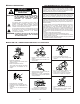
Connecting Other Souces Connecting a VCR • There are three sets of video deck (VCR) terminals, so three video decks can be connected for simultaneous recording or video copying. Video deck H VIDEO OUT I S VIDEO OUT H VIDEO IN I S VIDEO IN A AUDIO IN L L L R R R A AUDIO OUT L L L R R R NOTE: • When recording to VCR, it is necessary that the type of cable used with the playback source equipment be the same type that is connected to the AVR-4806 VCR-1 (to 3) OUTPUT terminal.
Connecting Other Souces Connecting a turntable • You can connect the turntable (MM cartridge) to the PHONO terminals. Turntable (MM cartridge) A L AUDIO OUT R GND NOTE: • The phono input can accept signals from moving magnet (MM) and high output moving coil (MC) phono cartridges. If your turntable is equipped with a low output MC cartridge, you will need to use a separate MC head amplifier or step-up MC transformer.
Connecting Other Souces Connectiong a tape deck Tape deck AUDIO IN A L L L R R R AUDIO OUT A L L R R L R DENON LINK connections • High quality digital sound with reduced digital signal transfer loss can be enjoyed by connecting a separately sold DENON LINK compatible DVD player.
Connecting Other Souces Connecting equipment with HDMI (High-Definition Multimedia Interface) terminals • A simple 1-cable connection (using a commercially available cable) with a device having an HDMI (High-Definition Multimedia Interface) connector allows digital transfer of the digital images of DVD video and other sources, and the multi-channel sound of DVD Audio and DVD Video. • To provide audio output from AVR-4806’s audio output connector, select “Amp” at the System Setup.
Connecting Other Souces Connecting equipment with DVI (Digital Visual Interface) terminals • Connection with equipment that has a DVI (Digital Visual Interface)-D connector permits the transfer of digital images. Make an analog or digital audio connection also. Monitor TV L HDMI IN K DVD player DVI-D OUT D OPTICAL OUT C COAXIAL OUT AUDIO OUT A L L L R R R • When connecting via a DVI-D cable, no digital audio will be output from the HDMI Monitor Out connector.
Connecting Other Souces Connecting IEEE1394 devices • For the digital transfer of signals from Super Audio CDs and DVD-Audio discs, connect using an IEEE1394 cable. For instructions on playing Super Audio CDs ( page 84). • Assign the IEEE1394 input the input source. For detailes, see “Setting the IEEE1394 Assign” ( page 92). DVD player F IEEE1394 2 IEEE1394 network q Up to 17 devices can be connected using daisy chain type connections. w Up to 63 devices can be connected using tree type connections.
Connecting Other Souces Connecting the antenna terminals • An F-type FM antenna cable plug can be connected directly. 2 AM loop antenna assembly FM ANTENNA AM LOOP ANTENNA (Supplied) 1 DIRECTION OF BROADCASTING STATION 2 Remove the vinyl tie and take out the connection line. Connect to the AM antenna terminals. 3 Bend in the reverse direction. 4 75 Ω/ohms COAXIAL CABLE a. With the antenna on top any stable surface. Mount b. With the antenna attached to a wall.
Connecting Other Souces Connecting the TRIGGER OUT terminals Turn the DC 12V voltage on and off for the individual functions and surround modes. For details, see “Setting the Trigger Out” ( page 109). Connecting the MULTI ZONE terminals For instructions on operations using the MULTI ZONE functions ( page 80 ~ 83).
Connecting Other Souces ZONE2/ZONE3 speaker out connections • When the power amplifier is assigned to the ZONE2 or ZONE3 output channel at “Power Amp Assign” in the “System Setup Menu”, the MAIN ZONE speaker terminals can be used as the ZONE2 or ZONE3 speaker out terminals ( page 106, 107). • The connections diagram below is an example for when the surround back speaker is assigned to the ZONE2 stereo 2 channel. In this case, Surround Back Speaker OUT can not be used for MAIN ZONE.
Connecting Other Souces Connecting the pre-out terminals • Use these terminals if you wish to connect external power amplifier(s) to increase the power of the front, center, surround and surround back sound channels, or for connection to powered loudspeakers. • When using only one surround back speaker, connect it to left channel.
Basic Operation Playback 2 SURROUND MENU Operating the remote control unit To select specific surround modes. • The RC-995 remote control has a backlit LCD screen whose contents change according to the mode or function selected, with the appropriate remote commands for that mode or function. Press the SURROUND button to display the screen below to choose a specific surround mode. 2 Operate the this unit The AMP button is the main mode for controlling the AVR-4806 in the main room (MAIN ZONE).
Basic Operation FUNCTION VOLUME SOURCE SURROUND HOME THX CINEMA FUNCTION VOLUME SOURCE HOME THX CINEMA ROOM EQ ROOM EQ Playing the input source 1 The volume can be adjusted within the range of –80 to +18 dB, in steps of 0.5 dB. However, when the channel level is set ( page 64, 65 or 116 ~ 118), if the volume for any channel is set at +0.5 dB or greater, the volume cannot be adjusted up to 18 dB. (In this case the maximum volume adjustment range is “18 dB — (Maximum value of channel level)”.
Basic Operation DIMMER VOLUME VOLUME ON SCREEN MUTING PHONES INPUT MODE SPEAKER EXT. IN VIDEO SELECT INPUT MODE ANALOG EXT. IN STATUS ANALOG Playback using the external input (EXT. IN) terminals Listening over headphone Connect the headphone to the PHONES jack. Press the EXT. IN button to switch the external input. • The pre-out output (including the speaker output) is automatically turned off when headphones are connected.
Basic Operation 2 Using the dimmer function Switching the surround speakers • Use this to change the brightness of the display. Press the SPEAKER button. Press the DIMMER button. The surround speakers switch as shown below each time the SPEAKER button is pressed. SURROUND A The display brightness changes in four steps (bright, medium, dim and off).
Basic Operation ROOM EQ ANALOG ANALOG ROOM EQ 2 Selecting the analog mode 2 Input signal display • DOLBY DIGITAL Press the ANALOG button to switch to the analog input. ANALOG (exclusive analog audio signal playback mode): The signals input to the analog input terminals are decoded and played. • DTS NOTE: • Input mode when playing DTS sources: Noise will be output if DTS-compatible CDs or LDs are played in the “ANALOG” or “PCM” mode.
Basic Operation Room EQ function • The AVR-4806’s Auto Setup / Room EQ function offers three correction curves: “Audyssey”, “Front”, “Flat”. The timbre of the speakers can also be adjusted manually using a graphic equalizer. Details of the different correction curves are described below. Audyssey: This adjusts the frequency response of all speakers to correct the effects of room acoustics. Front: This adjusts the characteristics of each speaker to the characteristics of the front speakers.
Basic Operation Surround Sources recorded in stereo Sources recorded in monaural Playing modes for different sources • The AVR-4806 is equipped with many surround modes. We recommend using the surround modes as described below in order to achieve the maximum effect for the specific signal source. PURE DIRECT ( page 49) • By suspending all circuits and processes not required, analog input music playback can be played with optimum quality. is a 6.1-channel/7.1-channel surround mode.
Basic Operation SURROUND PURE DIRECT PURE DIRECT DIRECT STEREO DIRECT/STEREO 2 STEREO mode Playing audio sources (CDs and DVDs) 2-channel playback modes Use this mode to adjust the tone and achieve the desired sound. • The AVR-4806 is equipped with three 2-channel playback modes exclusively for music. • Select the mode to suit your tastes. Press the DIRECT/STEREO button to select the STEREO mode. 2 PURE DIRECT mode This mode reproduces the sound with extremely high quality.
Basic Operation SURROUND PARAMETER ENTER STATUS SURROUND HOME THX CINEMA SURROUND BACK ENTER CURSOR ON SCREEN HOME THX CINEMA CURSOR SURROUND BACK SURROUND PARAMETER 2 Playing sources recorded in Dolby Surround in the Home THX cinema surround mode THX surround EX / Home THX cinema mode 1 2 • When the HOME THX CINEMA button is pressed, the surround mode is set as follows according to the signal that is played: q THX Surround EX (THX Ultra2 Cinema) w Home THX CINEMA (PLIIx C + THX) e THX 5.
Basic Operation 2 Surround parameters q • In addition, screen information is displayed in the following order when the ON SCREEN button is pressed repeatedly: OSD-1 Audio input signal OSD-2 Monitor information OSD-3 Input/output OSD-4 Auto surround mode OSD-5 USER MODE 1 OSD-6 USER MODE 2 OSD-7 USER MODE 3 OSD-8~14 Tuner preset stations DECODER: Select the decoder to be used when playing 2-channel sources in the Home THX Cinema mode.
Basic Operation STANDARD ENTER SURROUND PARAMETER SURROUND STANDARD SURROUND BACK ENTER CURSOR CURSOR SURROUND PARAMETER SURROUND BACK 2 Surround parameters w (2) (2ch source) OFF: Playback is conducted without using the surround back speaker. ON: Playback is conducted using the surround back speaker. This operation can be performed directly pressing the SURROUND BACK button. MODE/SB CH OUT: Select the surround back channel playback method or mode.
Basic Operation Example: When playing software that has a Dolby Digital EX flag Dolby Digital mode and DTS Surround (only with digital input) q When AFDM is set to “ON”, the surround mode is automatically set to the “DOLBY DIGITAL + PLIIx 1 2 CINEMA” mode. The surround parameter screen shown at the below is displayed. Press the STANDARD button to select the “STANDARD (Dolby/DTS Surround)” mode. Play a program source with the mark. • The Dolby Digital indicator lights when playing Dolby Digital sources.
Basic Operation 2 Surround parameters e 2 Dialogue Normalization The dialogue normalization function is activated automatically when playing Dolby Digital program sources. Dialogue normalization is a basic function of Dolby Digital which automatically normalizes the dialog level (standard level) of the signals which are recorded at different levels for different program sources, such as DVD, DTV and other future formats that will use Dolby Digital.
Basic Operation STANDARD SURROUND PARAMETER SURROUND STANDARD CURSOR F CURSOR F SURROUND PARAMETER CURSOR G Dolby Pro Logic IIx (Pro Logic II) mode 4 • To play in the PLIIx mode, set “Sp.Back” at the Speaker Configuration setting to “1spkr” or “2spkrs”. • To play in the PLIIx mode, set “Surround Back” at the Power Amp Assign setting. 1 2 Display *Surr MODE: • The Dolby Pro Logic indicator lights. The mode switches as shown below each time the STANDARD button is pressed.
Basic Operation STANDARD ENTER SURROUND PARAMETER SURROUND STANDARD ENTER CURSOR SURROUND PARAMETER CURSOR 5 Press the CURSOR D or H button to select the various surround parameters. • There are four Dolby Surround Pro Logic modes (NORMAL, PHANTOM, WIDE and 3 STEREO). The AVR-4806 sets the mode automatically according to the types of speakers set during the system setup process ( page 113, 114).
Basic Operation DTS NEO:6 mode • When “Default” is selected and the CURSOR F button is pressed, “MODE” and “TONE” are automatically reset to the default values and “CINEMA EQ.” is set to “OFF”. • When playing PCM digital signals or analog signals in the DOLBY PRO LOGIC II, DOLBY PRO LOGIC IIx, DTS NEO:6 modes and the input signal switches to a digital signal encoded in Dolby Digital, the Dolby Surround mode switches automatically.
Basic Operation ENTER SURROUND PARAMETER SURROUND ENTER USER MODE CURSOR PHONES CURSOR SURROUND PARAMETER USER MODE 2 Parameters The Dolby Headphone MODE: • DH1: Reference room (small room with weak reverberations). • DH2: Live room (room with a bit stronger reverberations than DH1). • DH3: Large room (larger room than DH1, offers a sense of distance and sound diffusion effects). • BYPASS: Stereo sound.
Basic Operation Memory and call-out functions (USER MODE function) • The AVR-4806 is equipped with a function for storing the selected input source, the auto surround mode and input mode in the memory and selecting these settings when you want to use them. • Three patterns of settings can be stored in the memory pressing the USER MODE buttons.
Basic Operation DENON original surround modes • The AVR-4806 is equipped with a high performance DSP (Digital Signal Processor) which uses digital signal processing to synthetically recreate the sound field. One of nine preset surround modes can be selected according to the program source and the parameters can be adjusted according to the conditions in the listening room to achieve a more realistic, powerful sound.
Basic Operation 7CH STEREO SURROUND PARAMETER ENTER SURROUND DSP SIMULATION ENTER 9CH (7CH STEREO) CURSOR DSP SIMULATION SURROUND PARAMETER CURSOR DSP surround simulation 1 3 4 5 Select the surround mode for each input channel. Example: DSP surround simulation mode (Remote control unit) (Remote control unit) SUPER STADIUM MATRIX VIDEO GAME 2 Press the ENTER or SURROUND PARAMETER button to complete the setting.
Basic Operation ENTER SURROUND PARAMETER ENTER CURSOR CURSOR SURROUND PARAMETER TONE DEFEAT 2 Surround parameters y EFFECT LEVEL: This sets the strength of the surround effect. The level can be set in 15 steps from 1 to 15. Lower the level if the sound seems distorted. EFFECT: This parameter turns the effect signals with multi surround mode speaker effects on and off in the WIDE SCREEN mode.
Basic Operation Tone control setting 5 6 • Use the tone control setting to adjust the bass and treble as desired. • The tone control function will not work in the PURE DIRECT, DIRECT or Home THX Cinema mode. Press the SURROUND PARAMETER button. • Display the surround parameter menu. 7 8 The screen selected surround mode appears. 2 Press the CURSOR F or G button to set the level. To increase the bass or treble: The bass or treble sound can be increased to up to +6 dB in steps of 1 dB.
Basic Operation TUNER ENTER FUNCTION SOURCE NUMBER / SYSTEM CALL FUNCTION TUNING ENTER CURSOR CURSOR BAND Channel Level Fader function • This function makes it possible to lower the volume of the front channels (FL, C and FR) or the rear channels (SL, SR, SBL and SBR) together. Use it for example to adjust the balance of the sound from each position when multi-channel music sources are played.
Basic Operation 3 Press the CURSOR F button to reduce the volume of the front channels, the CURSOR G button to reduce the volume of the rear channels. • The channel whose channel level is adjusted lowest can be faded to –12 dB using the fader function. • If the channel levels are adjusted separately after adjusting the fader, the fader adjustment values are cleared, so adjust the fader again. Example: When “FRONT” is selected The fader function does not affect the subwoofer channel.
Basic Operation TUNER SOURCE FUNCTION FUNCTION CHANNEL ON SCREEN TUNING PRESET RDS SHIFT Preset memory 1 2 MEMORY MEMORY BLOCK Checking the preset stations • The preset (broadcast) stations can be checked on the on screen display. Use the “Auto tuning” or “Manual tuning” operation to tune in the station to be preset in the memory. Press the ON SCREEN button repeatedly until the “Tuner Preset Stations” screen appears on the OSD. Press the TUNER button to select the TUNER mode.
Basic Operation 2 Recalling preset stations from the main unit’s panel 1 2 RDS search • Use this function to automatically tune to FM stations that provide RDS service. Press the TUNING PRESET button. 1 Turn the FUNCTION knob and select the desired preset channel. Set the input source to “TUNER”. (Main unit) RDS (Radio Data System) 2 • RDS (works only on the FM band) is a broadcasting service which allows station to send additional information along with the regular radio program signal.
Basic Operation CURSOR F FUNCTION SOURCE CURSOR G FUNCTION CHANNEL CURSOR G CURSOR F RDS PTY search 4 • Use this function to find RDS stations broadcasting a designated program type (PTY). • For a description of each program type, refer to “Program Type (PTY)”. 1 If there is no station broadcasting the designated program type with above operation, all the reception bands are searched. The station name is displayed on the display after searching stops.
Basic Operation TP search RT (Radio Text) • Use this function to find RDS stations broadcasting traffic program (TP stations). • “RT” appears on the display when radio text data is received. 1 1 Set the input source to “TUNER”. (Main unit) 2 (Remote control unit) (Remote control unit) Set the input source to “TUNER”. (Main unit) 2 Press the RDS button until “TP SEARCH” appears on the display.
Advanced Operation Remote control unit 2 MODE SELECTOR 3 Operate the audio component. For details, refer to the component’s operating instructions. It may not be possible to operate some models. 2 SOURCE MENU • Operate the source. Operating DENON audio components 1 Press the MODE SELECTOR buttons to select the component you want to operate. The function switches as shown below each time one of the MODE SELECTOR buttons is pressed.
Advanced Operation 1. CD player (CD) system buttons 6, 7 2 1 8, 9 3 0 ~ 9, +10 : : : : : : 2.
Advanced Operation 3. Tuner system buttons OFF ON MODE SELECTOR NUMBER ENTER Preset memory • The included remote control unit can be used to operate devices of different brands by registering the preset number corresponding to the brand of your device. For some models the remote control unit or the device may not operate properly. In this case, use the learning function ( page 76) to store your device’s remote control signals in the included remote control unit.
Advanced Operation 4 Operating a component stored in the preset memory Referring to the included List of Preset Codes, press the NUMBER to input the preset code (a 4-digit number) for the manufacturer of the component whose signals you want to store in the memory. 1 2 • “OK” is displayed when the signals are registered and the mode is terminated. “FAIL” is displayed when the signals are not registered, repeat steps 1 to 4. 5 To store the codes of another component in the memory, repeat steps 1 to 5.
Advanced Operation 1. DVD player (DVD), DVD recorder (DVD R) system buttons 2.
Advanced Operation 3. Video deck (VCR-1/VCR-2) system buttons 4.
Advanced Operation OFF 5 ON MODE SELECTOR Point the remote control units directly at each other and press and hold in the button on the other remote control unit which you want to “learn”. • “OK” appears on the remote control unit’s display and learning is completed. SYSTEM CALL NUMBER Other remote control unit ENTER ( ) Other keys can be “learned” by repeating steps 5. “FAIL” appears on the remote control unit’s display, repeating steps 4 and 5.
Advanced Operation System call • If you exceed the number of signals that can be registered, there will be a changeover to the system call registration screen. • The accessorius remote control unit is equipped with “system call” function allowing a series of remote control signals to be transmitted by pressing a single button.
Advanced Operation OFF Resetting ON 2 Resetting the preset memory MODE SELECTOR 1 2 3 NUMBER CHANNEL ENTER Press the 5 button to select Light setup. : : : : : Resetting the preset memory Resetting the “Learned” buttons Resetting the system call Resetting the punch through setting All reset function (factory default) • The MODE SELECTOR buttons that were set in preset memory will all light. Press the button you want to adjust the lighting time (5 sec ~ 20 sec).
Advanced Operation 2 Resetting the system call buttons 2 All reset function 1 2 3 Press the ON and OFF button at the same time. 1 2 3 4 Press the MODE SELECTOR button you want to resetting, then press the ENTER button. Press the 6 button to select resetting. Press the 3 button to resetting the system call buttons. • All buttons of system call will light. 2 Resetting the punch through setting Press the 4 button to resetting the punch through setting.
Advanced Operation Multi zone music entertainment system • When the outputs of the “ZONE2 (ZONE3)” OUT terminals are wired and connected to power amplifiers installed in other rooms, different sources can be played in rooms other than the MAIN ZONE in which this unit and the playback devices are installed. (Refer to ZONE2 (ZONE3) on the diagram below.
Advanced Operation Multi-zone playback using the SPEAKER terminals 2 When using the power amplifier as the ZONE2/ZONE3 output • When the power amplifier is assigned to the ZONE2 or ZONE3 output channel at “Power Amp Assign” in the “System Setup Menu”, the MAIN ZONE speaker terminals can be used as the ZONE2 or ZONE3 speaker out terminals ( page 106, 107).
Advanced Operation FUNCTION SOURCE OFF MODE SELECTOR ZONE3/REC SELECT SOURCE ON FUNCTION VOLUME ZONE2 SELECT MUTING Outputting a program source to an amplifier, etc., in a ZONE2 room (ZONE2 SELECT mode) 1 2 3 Outputting a program source to an amplifier, etc., in a ZONE3 room (ZONE3 SELECT mode) 1 Press the ZONE2 SELECT button to display the “ZONE2 SOURCE” on the display. Turn the FUNCTION knob to select the source you want to output appears on the display.
Advanced Operation Remote control unit operations during multi-source playback 1 Select the zone which you want to operate pressing the MODE SELECTOR buttons. Example: ZONE2 (Remote control unit) 2 Press the SOURCE ON button to turn on the zone power. Press the SOURCE OFF button to turn off the zone power. 3 4 Select the input source you wish to output. The volume of the outputs of the different zones can be adjusted with the VOLUME button on the remote control unit.
Advanced Operation Other function FUNCTION ZONE3/REC SELECT DIRECT/STEREO SOURCE SURROUND FUNCTION SURROUND MODE STEREO DIRECT ON SCREEN SURROUND PHONES INPUT MODE MODE When playing DSD signals in the DIRECT or PURE DIRECT mode, the DSD signals are converted into analog signals. When playing in other surround modes, the DSD signals are first converted into PCM signals with a sampling frequency of 88.2 kHz.
Advanced Operation 2 Recording Dolby Digital and DTS multichannel sources Multi-source recording / playback • With this set it is possible to record Dolby Digital and DTS multichannel signals converted into 2-channel analog signals. • The recording signals are output to the TAPE and VCR output terminals. • Down-mixed analog signals converted into digital signals are output from the OPTICAL 2, 3 and 4 digital output terminals at this time.
Advanced Operation POWER Initialization of the Microprocesssor DIRECT/STEREO • In very rare instances, the AVR-4806 internal microprocessor might lock up, or otherwise cause mis-operation. This might be caused due to an AC line surge or line spike noise, or by static electric discharge on or nearby the unit, or to connected components.
Advanced Setup – Part 1 • You can customize a variety of system setup so that it may be fitting for your listening environment. For the contents of a system memu and the initial setting of this unit ( page 126 ~ 128). Navigating through the System Setup Menu • You can change setting using the buttons on the front panel or remote control unit. CURSOR D CURSOR F ENTER AMP ENTER CURSOR D CURSORF CURSOR G SETUP CURSORH CURSOR G SETUP 1 2 3 4 5 6 Press the AMP button on the remote control unit.
Advanced Setup – Part 1 On screen display and front display • The AVR-4806 is equipped with an intuitive and easy-to-understand on screen display, and is equipped with an alpha-numeric front panel display tube that can also be used to check and adjust settings. We recommend that you use the on screen display when you make system adjustments. Some representative front panel and on screen display examples are shown below.
Advanced Setup – Part 1 Audio Input Setup • Make the audio-related settings. Setting the Digital In Assignment 3 • This setting assigns the digital input terminals of the AVR4806 for the different input sources. 1 Select from among COAX 1 to 3, OPT 1 to 5. If the same digital input terminal is selected, the setting for the input source that was previously assigned switches to “OFF”. The HDMI input terminal is displayed when it is assigned to the input source at “HDMI/DVI In Assign” ( page 96, 97).
Advanced Setup – Part 1 Setting the DENON LINK Setting the EXT. IN Setup • Set the method of playback of the analog input signal connected to the EXT. IN (8CH) terminal. • Refer to “Connecting the external inputs (EXT. IN) terminals” ( page 30). • When a DENON DVD player and the DENON LINK have been connected, be sure to make a setting to “DENON LINK” with the System Setup Digital In Assignment.
Advanced Setup – Part 1 Setting the Input Function Level Setting the Function Rename • Correct the playback level of the different input sources. • Adjust the playback levels of the devices connected to the different input sources to the same level to eliminate the need for adjusting the main volume each time the input source is switched. 1 • The names of the input sources displayed on the front display and on the on-screen display can be changed.
Advanced Setup – Part 1 Setting the IEEE1394 Assign If you wish to set the input source back to as it was initially, press the CURSOR H button with the input source highlighted. If “Yes” is selected for “Default”, the setting are automatically reset to the default name. • Assign the device connected by IEEE1394 cable to an input source. The power of the device to be assigned must be turned on ahead of time.
Advanced Setup – Part 1 Setting the IEEE1394 Auto Function Tuner Presets • Set whether or not to automatically play the IEEE1394 device when it is selected with the FUNCTION knob. 1 2 Auto Preset Memory • Use this to automatically search for FM broadcasts and store up to 56 stations at preset channels A1 to 8, B1 to 8, C1 to 8, D1 to 8, E1 to 8, F1 to 8 and G1 to 8. Press the CURSOR D or H button to select the “IEEE1394 Auto Func.” at the “Audio Input Setup” menu, then press the ENTER button.
Advanced Setup – Part 1 2 Preset Skip 2 Preset Name • When selecting preset channels pressing the PRESET button, it is possible to skip specific preset channels. 1 • It is possible to input station names , etc., for preset channels. These names are displayed on the front display and on the on screen display. Press the CURSOR D or H button to select the “Preset Skip” at the “Tuner Presets” screen, then press the ENTER button. 1 • Switch to the “Preset Skip ”screen.
Advanced Setup – Part 1 4 9 Repeat step 3 to input the preset channel name. If you wish to set the preset channel name back to as it was initially, press the CURSOR H button with the preset channel name highlighted. If “Yes” is selected for “Default”, the setting are automatically reset to the default name. 5 Once all the characters have been input, press the ENTER button. • The “Preset Name” screen reappears. Use the same procedure to change other input source names as well.
Advanced Setup – Part 1 Video Setup • Make the video-related settings. Setting the HDMI / DVI In Assign 4 • This setting assigns the HDMI input terminals and DVI input terminal for different input sources. • Set the method for playing the audio signals included in the HDMI input signal. Press the CURSOR D or H button to select the method for playing the audio signals included in the HDMI input signal, then press the CURSOR F or G button to select the “TV” or “AMP”.
Advanced Setup – Part 1 Setting the Video Convert Mode • If a monitor is connected with an HDMI cable but the monitor is not compatible with HDMI audio signal playback, only the video signals are output to the monitor from the AVR-4806 (DVI mode). Press the STATUS button to check which mode is set for outputting HDMI signals from the AVR-4806 (HDMI and DVI modes). • Input signals input from the analog and digital terminals are not output to the TV.
Advanced Setup – Part 1 Setting the HDMI Out Setup Video: The signal connected to the composite video terminal is always played. The composite video input signal is up-converted and output from the S-Video and component monitor output terminals. • Set whether to use the analog video signals to HDMI conversion function. • When using this conversion function, set the color format and video range of the signals output from the HDMI terminal. OFF: The convert function does not operate.
Advanced Setup – Part 1 Setting the Audio Delay • “Color Space” and “RGB Mode Setup” are only displayed when “Analog to HDMI Convert” is set to “ON”. • When connecting to an HDCP compatible monitor equipped with DVI-D terminal using an HDMI/DVI-D converter cable, the signals are output in RGB format, regardless of the “Color Space” setting. • To view the on-screen display using an HDMI monitor, set “Analog to HDMI Convert” at “HDMI Out Setup” to “ON” (default).
Advanced Setup – Part 1 Setting the On Screen Display (OSD) • Use this to turn the on screen display (messages other than the menu screens) on or off. • Sets the on screen display’s display mode. 1 4 Press the CURSOR D or H button to select the “On Screen Display” at the “Video Setup” menu, then press the ENTER button. • Display the “On Screen Display” screen. 2 Press the CURSOR D or H button to select the item to be set, then press the CURSOR F or G button to select the parameter.
Advanced Setup – Part 1 Advanced Playback • Makes more detailed audio playback settings. Setting the 2ch Direct/Stereo • Set this when you want to change the speaker settings when the surround mode is set to the 2-channel Direct or Stereo mode. 1 3 Press the CURSOR F or G button to select the “Custom”. 4 Press the CURSOR D or H button to select the setting, then press the CURSOR F or G button to select the parameter. 5 Press the ENTER button to enter the setting.
Advanced Setup – Part 1 Setting the Dolby Digital Setup Setting the Auto Surround Mode • Sets the down-mixing method when not using a center speaker or surround speakers. 1 Press the CURSOR D or H button to select the “Dolby Digital Setup” at the “Advanced Playback” menu, then press the ENTER button. • Display the “Dolby Digital Setup” screen. 2 Press the CURSOR F or G button to select the “ON” if you want to use the Compression, “OFF” if you do not want to use it.
Advanced Setup – Part 1 Setting the Manual EQ Setup w Select the “Each CH” FL • Allows you to adjust the tonal quality of the various speakers (except the subwoofer) while listening to a music source. 1 SBR SB Press the CURSOR D or H button to select the “Manual EQ Setup” at the “Advanced Playback” menu, then press the ENTER button. SLA FR C SBL SR A+B SRA SL A+B SLB SRB 1spkr When the surround back speaker setting is set to “1spkr” at “Speaker Configuration”, this is set to “SB”.
Advanced Setup – Part 1 7 Procedure for copying the “Flat” correction curve Press the CURSOR D or H button to select the “Exit”, then press the ENTER button. • The “System Setup Menu” reappears. • “Base Curve Copy” is displayed after performing the Auto Setup. • To restore the settings to their defaults, select “Default Yes 0”, then press the CURSOR F button. 1 Press the CURSOR D button to select the “Base Curve Copy”, then press the CURSOR F button. 2 Press the CURSOR F button to select the “Yes”.
Advanced Setup – Part 1 Option Setup • Make other expert settings. Setting the Channel Setup • With this setting it is possible to change the number of channels played in the different zones according to the purpose. This configures the AVR-4806 according to whether or not you have surround “B” speakers connected, and whether or not you have surround back (SB) speaker(s) connected.
Advanced Setup – Part 1 Setting the Power Amplifier Assignment • AVR-4806’s power amplifiers for seven channels (except the front channel), can be assigned to any channels in the MAIN ZONE, ZONE2 or ZONE3 and output to the speakers. In this way, power amplifiers not being used in the MAIN ZONE can be assigned for multi-zone use, the front speakers can be connected with a “Bi-Amp”, etc., so you can create the desired speaker system.
Advanced Setup – Part 1 S. Back: If no surround back speakers are used in the main room, their amplifier channels can be assigned for other uses, or one of the two channels can drive one surround back speaker in the main room, while the other channel can drive a monaural speaker in another zone. • Front: This provides a bi-amp mode for the two main front speakers, replicating the front left and front right amplifier channels’ outputs.
Advanced Setup – Part 1 Setting the Volume Control Power On Level: Set the volume that is set when the power is turned on for the different zones. You can adjust the volume level within the range of –80 to +18 dB in steps of 1.0 dB. • – – – (Mute) The volume is always muted when the power is turned on. • LAST The volume set when the AVR-4806 was last used is stored in the memory and set when the power is turned on.
Advanced Setup – Part 1 Setting the Trigger Out • Three 12 V DC Trigger Outputs on the rear panel can be used to control other devices with compatible trigger inputs, such as motorized screens, motorized screen masking, motorized drapes, and other trigger-controlled devices. • Set the DC output supplied from the trigger out terminals for the various input sources to “ON” or “OFF”.
Advanced Setup – Part 1 ZONE2 and ZONE3 tone control and channel level setting 3 • Adjust the sound output from ZONE2 and ZONE3. 1 Press the CURSOR D or H button to select the item to be set, then press the CURSOR F or G button to adjust the parameter. Bass: Adjust the tone for the bass. Press the CURSOR D or H button to select the “Zone2/3 Tone/Ch Lev.” at the “Option Setup” menu, then press the ENTER button. Treble: Adjust the tone for the treble.
Advanced Setup – Part 1 Setting the Digital Out Assignment User Memory • The optical digital output connectors on the AVR-4806’s rear panel (OPTICAL2 to 4 OUT) normally function in association with the ZONE3/REC SELECT mode. With this setting, the OPTICAL 2 OUT connector can be used in association with the ZONE2 SELECT mode. 1 Press the CURSOR D or H button to select the “Digital Out Assign” at the “Option Setup” menu, then press the ENTER button.
Advanced Setup – Part 1 Setup Lock • The system setup settings can be locked so that they cannot be changed easily. 1 Press the CURSOR D or H button to select the “Setup Lock” at the “Setup Memory / Lock” screen, then press the ENTER button. • Switch to the “Setup Lock” screen. 2 • When the setup lock function is activated, the settings listed below cannot be changed, and “Setup Locked” is displayed when related buttons are operated.
Advanced Setup – Part 2 • This Speaker Setup section describes the procedures to make speaker settings manually (without using the Auto Setup function), as well as to make manual changes to settings that have already been made by the Auto Setup function. ENTER ENTER CURSOR SETUP SETUP CURSOR Speaker Setup • If the “Auto Setup” procedure has already been performed, there is no need to make this setting. • Perform this setting if you wish to make the settings for your speaker systems manually.
Advanced Setup – Part 2 Setting the low frequency distribution • Select “Large” or “Small” not according to the actual size of the speaker but according to the speaker’s capacity for playing low frequency (bass sound below the frequency set for the Crossover Frequency) signals. If you do not know, try comparing the sound at both settings (setting the volume to a level low enough so as not to damage the speakers) to determine the proper setting.
Advanced Setup – Part 2 2 Assignment of low frequency signal range • The only signals produced from the subwoofer channel are LFE signals (during playback of Dolby Digital or DTS signals) and the low frequency signal range of channels set to “Small” in the setup menu. The low frequency signal range of channels set to “Large” are produced from those channels. 1 Press the CURSOR D or H button to select the “Delay Time” at the “Speaker Setup” menu, then press the ENTER button.
Advanced Setup – Part 2 4 Press the CURSOR F or G button to set the distance between the center speaker and listening position. Example: When the distance is set to 12 feet for the center speaker The distance changes in units of 0.1 foot (0.03 meters) or 1 foot (0.3 meters) each time the button is pressed. Select the value closest to the measured distance. If “Yes” is selected for “Default”, the settings are automatically reset to the default values.
Advanced Setup – Part 2 3 Press the CURSOR D or H button to select the “Surr. Sp.”, then press the CURSOR F or G button to select the surround speaker(s) from which you want to produce the test tone (A, B or A+B). Example: When the volume is set to –11.5 dB while the test tone is being produced from the Front Lch speaker Surr. Sp. : A Adjusts the balance of the playback level between the channels when using surround speaker A. Surr. Sp.
Advanced Setup – Part 2 • When adjusting the level of an active subwoofer system, you may also need to adjust the subwoofer’s own volume control. • When you adjust the channel levels while in the SYSTEM SETUP CHANNEL LEVEL mode, the channel level adjustments made will affect all surround modes. Consider this mode a Master Channel Level adjustment mode.
Advanced Setup – Part 2 • If “LFE+Main” is set at “Subwoofer Setup”, “SW:LFE+Main” ( page 114, 115) is displayed at the top right of the screen. • Please set all THX Certifies speakers to small and the crossover to 80Hz. • We recommend using with the crossover frequency set to “FIXED–THX–”, but depending on the speaker, setting it to a different frequency may improve frequency response near the crossover frequency.
Advanced Setup – Part 2 2 Press the CURSOR D or H button to select the surround mode, then press the CURSOR F or G button to select the surround speaker. 2 Press the CURSOR D or H button to select the “Boundary Gain Compensation”, then press the ENTER button. A: 3 Press the CURSOR F or G button, when using a THX Ultra2 compatible subwoofer or subwoofer that frequency response extends to 20 Hz, select “Yes”. Otherwise select “No”. When surround speakers A is used. B: When surround speakers B is used.
Advanced Setup – Part 2 Surround Back Speaker Position Settings • When two surround back speakers have been set in “Speaker Configuration” ( page 113, 114), set the distance of the speakers. There is not displayed when “1spkr” selected. • This setting is necessary to achieve the optimum effect in the THX Surround EX, THX Ultra2 Cinema, THX Music mode and THX Games mode. It is recommended that SBL/SBR speakers are placed together as close as possible.
Advanced Setup – Part 2 Others Setup Setting the Room EQ Setup w Press the CURSOR F or G button to select the equalizer setting. • Select the setting of an Equalizer that has been set with Auto Setup or Manual EQ. 1 OFF: The Equalizer is not used. Audyssey: Adjusts the frequency response of all speakers to correct the effects of room acoustics. Press the CURSOR D or H button to select the “Room EQ Setup” at the “Auto Setup / Room EQ” menu, then press the ENTER button.
Advanced Setup – Part 2 Setting the Direct Mode Setup Setting the MIC Input Select • Perform the ON/OFF setting of Room EQ when the surround mode is “DIRECT” or “PURE DIRECT”. 1 Press the CURSOR D or H button to select the “Direct Mode Setup” at the “Auto Setup / Room EQ” menu, then press the ENTER button. • Sets whether the setup microphone is connected to the PIN JACK (V.AUX L channel) connector or the MINI JACK (SETUP MIC) connector. 1 • Display the “Mic Input Select” screen.
Advanced Setup – Part 2 Pressure level with SPL meter at the microphone point. Adjust AVR volume SPL meter = 80 dB (C) AVR-4806 Speaker Microphone (7) (8) (9) (10) (11) (12) (13) Set the Parameter “Test Tone” to “Manual” and “Test Tone Start” to “Yes” at “Channel Level” ( page 116 ~ 118). Once the test tone for Front Left (FL) speaker starts, check the Sound Pressure Level at the Listening Position with an SPL Meter. You do not have to check any of the other channels.
Advanced Setup – Part 2 4 Press the CURSOR D or H button to select the Equalizer curve, then press the ENTER button. 8 The results of the “Auto Setup” procedure can be reset even if the settings have been changed after performing the “Auto Setup” procedure: Press the CURSOR D or H button to select the “Restore Yes 0”, then press the CURSOR F button. 9 Press the CURSOR D or H button to select the “Exit”, then press the ENTER button.
Advanced Setup – Part 2 System setup items and default values (set upon shipment from the factory) 1. Auto Setup/Room EQ Default settings Page 1 Auto Setup This unit performs an analysis of the speaker system and measures the acoustic characteristics of your room to permit an appropriate automatic setting. Auto Setup / Room EQ – 19~25 2 Room EQ Setup Set the Room EQ setting with All or Assign for each surround mode.
Advanced Setup – Part 2 3. Audio Input Setup Audio Input Setup 1 Digital In Assign This assigns the digital input terminals for the different input sources. Default settings Input source Digital Inputs CD DVD VDP TV COAX 1 COAX 2 COAX 3 OPT 1 DBS VCR-1 VCR-2 VCR-3 OFF OPT 2 OPT 3 OFF OPT 4 V.AUX OPT 5 89, 90 Surr.Sp = Surr.A, SW Level = +15dB 2 EXT.IN Setup Set the Ext.In terminal playback method.
Advanced Setup – Part 2 6. Option Setup Option Setup Default settings Channel 1 Setup Main Zone The number of channels that you wish to play back in each zone are assigned to each zone accordingly. Surr.B = Used, S.Back = 2sp Power Amp 2 Assign To suit your preference, a power amp other than the front can be assigned to a playback channel, and the front channel bi-amp playback, or the ZONE2 or ZONE3 playback channel can be output from the AVR-4806 speakers.
Troubleshooting If a problem should arise, first check the following. 1. Are the connections correct? 2. Have you operated the receiver according to the Operating Instructions? 3. Are the speakers, and other connected components operating properly? If this unit is not operating properly, check the items listed in the table below. Should the problem persist, there may be a malfunction. Disconnect the power immediately and contact your store of purchase.
Troubleshooting Symptom Cause Measures Page • AVR-4806’s HDMI output terminals and • Check the HDMI connection. monitor’s input terminals are not properly connected. • No HDMI/DVI-D signal is being input. • Properly select HDMI or DVI-D signal input source. • The connected monitor equipment or other • The AVR-4806 will not output video signal equipments do not support HDCP. unless the other equipment supports HDCP.
Additional Information • Other types of audio: These signals are designed to recreate a 360° sound field using three to five speakers. Optimum surround sound for different sources There are currently various types of multi-channel signals (signals or formats with more than two channels). FL SW C FR 2 Types of multi-channel signals Dolby Digital (including Surround EX), DTS (including Surround ES), DVD-Audio, and Super Audio CD. Note on the above: MUSE 3.
Additional Information Surround back speakers The THX Surround EX format adds new “Surround Back” (SB) channels to the conventional 5.1-channel system. This makes it easy to achieve sound positioned directly behind the listener, something that was previously difficult with sources designed for conventional multi surround speakers.
Additional Information • When using two surround back speakers, set them at the back facing front and with both speakers at the same distance from the listening point. When using one surround back speaker, place it at the rear center facing the front at a slightly higher position (0 to 20 cm) than the surround speakers. • We recommend installing the surround back speaker(s) at a slightly downward facing angle.
Additional Information • Set the front speakers, center speaker and subwoofer in the same positions as in example (1). • It is best to place the surround speakers directly at the side or slightly to the front of the viewing position, and 60 to 90 cm above the ears. • Same as surround back speaker installation method (1). • Connect the surround speakers to the surround speaker A terminals on the AVR-4806 and set settings on the setup menu to “A”. (This is the factory default setting ( page 126).
Additional Information [2] When not using surround back speakers Surround Front speakers Center speaker The AVR-4806 is equipped with a digital signal processing circuit that lets you play program sources in the surround mode to achieve the same sense of presence as in a movie theater. Monitor Subwoofer [1] Dolby Surround 45° q Dolby Digital Dolby Digital is the multi-channel digital signal format developed by Dolby Laboratories. Dolby Digital consists of up to “5.
Additional Information Sources recorded in Dolby Surround • These are sources in which three or more channels of surround have been recorded as two channels of signals using Dolby Surround encoding technology. • Dolby Surround is used for the sound tracks of movies recorded on DVDs, LDs and video cassettes to be played on stereo VCRs, as well as for the stereo broadcast signals of FM radio, TV, satellite broadcasts and cable TV.
Additional Information [2] DTS Digital Surround 1: DTS Digital Surround (also called simply DTS) is a multichannel digital signal format developed by Digital Theater Systems. DTS offers the same “5.1” playback channels as Dolby Digital (front left, front right and center, surround left and surround right) as well as the stereo 2-channel mode.
Additional Information [3] DTS-ES Extended Surround™ DTS-ES Extended Surround is a new multi-channel digital signal format developed by Digital Theater Systems Inc. While offering high compatibility with the conventional DTS Digital Surround format, DTS-ES Extended Surround greatly improves the 360-degree surround impression and space expression thanks to further expanded surround signals. This format has been used professionally in movie theaters since 1999. In addition to the 5.
Additional Information [4] DTS 96/24 [5] Home THX Cinema Surround The sampling frequency, number of bits and number of channels used for recording of music, etc., in studios has been increasing in recent years, and there are a growing number of high quality signal sources, including 96 kHz/24 bit 5.1-channel sources. For example, there are high picture/sound quality DVD video sources with 96 kHz/24 bit stereo PCM audio tracks.
Additional Information 2 THX Games Mode 2 THX Ultra2™ Before any home theater component can be THX Ultra2 certified, it must incorporate all the features above and also pass a rigorous series of quality and performance tests. Only then can a product feature the THX Ultra2 logo, which is your guarantee that the Home Theater products you purchase will give you superb performance for many years to come.
Additional Information [6] THX Surround EX In 1999, a new surround system was launched simultaneously with the release of the movie “Star Wars Episode I”. “Dolby Digital Surround EX” is a new movie sound track that greatly enhances the sense of spatial expression and the positioning of the surround channel sound. The result is 360 degrees of movement and moving sound effects that seem to pass right over the listener’s head.
Additional Information The two diagrams below illustrate two examples of microphone placement for two types of seating arrangements. There are six measuring positions shown in each case. Increasing the number of measuring points will provide a better sampling of the listening area and produce better results. The dotted line represents the area in which the room correction provided by Audyssey MultEQ XT is optimal. The microphone must be placed at ear height at each location.
Additional Information About IEEE1394 About HDMI IEEE1394 is an international standard established by the Institute of Electrical and Electronics Engineers (IEEE) of the United States. The AVR-4806 can be connected to an IEEE1394 compatible device using an IEEE1394 cable to enable digital transfer of multi-channel audio sources (DVD Audio discs, Super Audio CDs, etc.) with a single cable. • The AVR-4806’s transfer format is compatible with A&M protocol.
CENTER E E B B E B B B B B B B B B B B B B B B B B B FRONT L/R C C C C C C C C C C C C C C C C C C C C C C C C : Signal / Adjustable E : No signal / Not adjustable B : Turned on or off by speaker configuration setting PURE DIRECT, DIRECT DSD DIRECT DSD MULTI DIRECT MULTI CH DIRECT STEREO EXT.IN MULTI CH IN WIDE SCREEN HOME THX CINEMA (2ch) HOME THX CINEMA (5.
E E E E E E E E E E E E E E E E E E E E E E C (30 msec) C C E E E E E E E E E E E E E E E E E E E E E SUBWOOFER DELAY TIME ON/OFF C : Signal / Adjustable E : No signal / Not adjustable B : Turned on or off by speaker configuration setting PURE DIRECT, DIRECT DSD DIRECT DSD MULTI DIRECT MULTI CH DIRECT STEREO EXT.IN MULTI CH IN WIDE SCREEN HOME THX CINEMA (2ch) HOME THX CINEMA (5.
HOME THX CINEMA ES DSCRT6.1 + THX ES MTRX6.1 + THX THX SURROUND EX THX Ultra2 Cinema THX Music Mode THX Games mode THX 5.1 PLIIx C + THX PLII C + THX DOLBY PL + THX NEO:6 + THX STANDARD DTS SURROUND DTS ES DSCRT6.1 DTS ES MTRX6.
Mode selectable in initial status Mode fixed when AFDM is ON Selectable mode Non-selectable mode C C C C C C C C C 4 C C C C C C C C C 4 *2 *1 *3 C E E E E E C E E E E E *2 *1 LINEAR PCM C E E E E E ANALOG C E E E E E Note C E E E E E C E E E E E C C C C C C C C C C C E E E E E C C C C C C C C C C C E E E E E C C C C C C C C C C DTS (5.
Additional Information Relationship between the video input signal and monitor output according to the video convert mode settings Video convert mode AUTO Input signals HDMI E E E E E E E E E E E E E E E E C C C C C C C C C C C C COMPONENT E E E E C (1080p) C (480p ~ 720p) C (480i/576i) C (1080p) C (480p ~ 720p) C (480i/576i) C (1080p) C (480p ~ 720p) C (480i/576i) C (1080p) C (480p ~ 720p) C (480i/576i) E E E E C (Other than 480i/576i) C (480i/576i) C (Other than 480i/576i) C (480i/576i) C (Other than
Additional Information Video convert mode COMPONENT HDMI E E E E E E E E E E E E E E E E C C C C C C C C C C C C C C C C Input signals COMPONENT E E E E C (1080p) C (480p ~ 720p) C (480i/576i) C (1080p) C (480p ~ 720p) C (480i/576i) C (1080p) C (480p ~ 720p) C (480i/576i) C (1080p) C (480p ~ 720p) C (480i/576i) E E E E C (1080p) C (480p ~ 720p) C (480i/576i) C (1080p) C (480p ~ 720p) C (480i/576i) C (1080p) C (480p ~ 720p) C (480i/576i) C (1080p) C (480p ~ 720p) C (480i/576i) S-VIDEO VIDEO E E E C C E C
Specifications 2 Audio section • Power amplifier Rated output: Dynamic power: Output terminals: • Analog Input sensitivity / input impedance: Frequency response: S/N: Distortion: Rated output: • Digital D/A output: Front: 140 W + 140 W (8 Ω/ohms, 20 Hz ~ 20 kHz with 0.05 % 165 W + 165 W (6 Ω/ohms, 20 Hz ~ 20 kHz with 0.05 % Center: 140 W (8 Ω/ohms, 20 Hz ~ 20 kHz with 0.05 % T.H.D.) 165W (6 Ω/ohms, 20 Hz ~ 20 kHz with 0.05 % T.H.D.) Surround (A, B): 140 W + 140 W (8 Ω/ohms, 20 Hz ~ 20 kHz with 0.
Specifications 2 Tuner section Receiving Range: Usable Sensitivity: 50 dB Quieting Sensitivity: S/N (IHF-A): Total Harmonic Distortion (at 1 kHz): [FM] (note: µV at 75 Ω/ohms, 0 dBf = 1 x 10–15 W) 87.5 MHz ~ 107.9 MHz 1.0 µV (11.2 dBf) MONO 1.6 µV (15.3 dBf) STEREO 23 µV (38.5 dBf) MONO 77 dB STEREO 72 dB MONO 0.15% STEREO 0.3% [AM] 520 kHz ~ 1710 kHz 18 µV 50 dB 2 General Power supply: Power consumption: Maximum external dimensions: Mass: AC 120 V, 60 Hz 10.
MEMO: 152
MEMO: 153
TOKYO, JAPAN www.denon.com Denon Brand Company, D&M Holdings Inc.