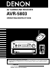
AV SURROUND RECEIVER AVR-5803 OPERATING INSTRUCTIONS MASTER VOLUME INPUT SELECTOR VOLUME LEVEL REMOTE SENSOR INPUTSIGNAL LOCK AUTO DIGITAL SURROUND BACK CH OUTPUT AL24 INPUT MODE PCM DTS RF SIGNAL DETECT ·)) ON / STANDBY HOME THX CINEMA PURE DIRECT SURROUND SPEAKER A B PHONO CD TUNER DVD VDP TV DBS / SAT VCR-1 VCR-2 VCR-3 V.
SAFETY PRECAUTIONS CAUTION CAUTION TO PREVENT ELECTRIC SHOCK, MATCH WIDE BLADE OF PLUG TO WIDE SLOT, FULLY INSERT. RISK OF ELECTRIC SHOCK DO NOT OPEN CAUTION: TO REDUCE THE RISK OF ELECTRIC SHOCK, DO NOT REMOVE COVER (OR BACK). NO USER-SERVICEABLE PARTS INSIDE. REFER SERVICING TO QUALIFIED SERVICE PERSONNEL.
SAFETY INSTRUCTIONS 1. 2. 3. 4. 5. 6. 7. 8. 9. 10. 11. 12. Read Instructions – All the safety and operating instructions should be read before the product is operated. Retain Instructions – The safety and operating instructions should be retained for future reference. Heed Warnings – All warnings on the product and in the operating instructions should be adhered to. Follow Instructions – All operating and use instructions should be followed.
2 INTRODUCTION Thank you for choosing the DENON AVR-5803 Digital Surround A / V receiver. This remarkable component has been engineered to provide superb surround sound listening with home theater sources such as DVD, as well as providing outstanding high fidelity reproduction of your favorite music sources. As this product is provided with an immense array of features, we recommend that before you begin hookup and operation that you review the contents of this manual before proceeding.
3 CAUTIONS ON HANDLING • Switching the input function when input jacks are not connected A clicking noise may be produced if the input function is switched when nothing is connected to the input jacks. If this happens, either turn down the MASTER VOLUME control or connect components to the input jacks. • Whenever the power switch is in the STANDBY state, the apparatus is still connected on AC line voltage. Please be sure to unplug the cord when you leave home for, say, a vacation.
14.Seven Identical Power Amplifiers Featuring discrete high current power transistors, the power amp section is THX Ultra certified for top performance with the widest range of speaker systems. Rated at 170 watts into 8 Ω/ohms, the amp channels feature additional low impedance drive capability. 15.Future Sound Format Upgrade Capability via Eight Channel Inputs & Outputs For future multi-channel audio format(s), the AVR-5803 is provided with 7.
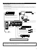
Connecting the audio components • When making connections, also refer to the operating instructions of the other components. CD recorder or Tape deck 1 MD recorder or Tape deck 2 OUTPUT INPUT OUTPUT INPUT R L R L R L R L R L R L R L R L B Connecting a tape deck Connections for recording: Connect the tape deck’s recording input jacks (LINE IN or REC) to this unit’s tape recording (OUT) jacks using pin plug cords.
Connecting video components • To connect the video signal, connect using a 75 Ω/ohms video signal cable cord. Using an improper cable can result in a drop in picture quality. • When making connections, also refer to the operating instructions of the other components. Connecting a TV/DBS tuner TV or DBS tuner AUDIO R R OUT L TV/DBS • Connect the TV’s or DBS tuner’s video output jack (VIDEO OUTPUT) to the VIDEO (yellow) TV/DBS IN jack using a 75 Ω/ohms video coaxial pin plug cord.
Connecting a video component equipped with S-Video jacks • When making connections, also refer to the operating instructions of the other components. • A note on the S input jacks The input selectors for the S inputs and pin jack inputs work in conjunction with each other.
Connecting a Video Component Equipped with Color Difference (Component - Y, PR/CR, PB/CB) Video Jacks (DVD Player) • When making connections, also refer to the operating instructions of the other components. • The signals input to the color difference (component) video jacks are not output from the VIDEO output jack (yellow) or the S-Video output jack. • Some video sources with component video outputs are labeled Y, PB, PR, or Y, CB, CR, or Y, R-Y, B-Y.
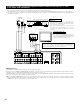
Connecting the antenna terminals DIRECTION OF BROADCASTING STATION AM LOOP ANTENNA (Supplied) FM ANTENNA F-type converter plug (attached) • When using the FM antenna attach to this apparatus FEEDER CABLE IN Y FRONT 75 Ω/ohms COAXIAL CABLE R CONPONENT VIDEO MULTI ZONE 1 CENTER ANTENNA TERMINALS DVD VDP CD DVD VDP FRONT CENTER SURR. VIDEO OUT SURR.-A R AM LOOP ANT. S-VIDEO SURR.-B R FMCOAX. 75Ω 300 Ω/ohms FM INDOOR ANTENNA (Supplied) SURR.
Connecting the external input (EXT. IN) jacks • These jacks are for inputting multi-channel audio signals from an outboard decoder, or a component with a different type of multi-channel decoder, such as a DVD Audio player, or a multi-channel SACD player, or other future multi-channel sound format decoder. • When making connections, also refer to the operating instructions of the other components. 1 CENTER SAT VIDEO ANTENNA TERMINALS OUT SURR.-A R AM S-VIDEO LOOP ANT. IN OUT SURR.
Speaker system connections • Connect the speaker terminals with the speakers making sure that like polarities are matched ( < with < , > with > ). Mismatching of polarities will result in weak central sound, unclear orientation of the various instruments, and the sense of direction of the stereo being impaired. • When making connections, take care that none of the individual conductors of the speaker cord come in contact with adjacent terminals, with other speaker cord conductors, or with the rear panel.
Connections • When making connections, also refer to the operating instructions of the other components. Connection jack for subwoofer with built-in amplifier (super woofer), etc. FRONT SPEAKER SYSTEMS (L) SURROUND SPEAKER SYSTEMS (A) CENTER SPEAKER SYSTEM (R) (L) (R) IN IN Y FRONT R DVD P B/C B P R/C R TV P B/C B P R/C R IN Y IN Y DBS / SAT P B/C B P R/C R MONITOR OUT P B/C B P R/C R Y MULTI ZONE 1 CENTER ANTENNA TERMINALS L DVD VDP TV DBS / SAT V.
6 PART NAMES AND FUNCTIONS Front Panel • For details on the functions of these parts, refer to the pages given in parentheses ( ). #5 #4 #3 #2 #1 #0 @9 @8 @7 @6 @5 @4 MASTER VOLUME INPUT SELECTOR VOLUME LEVEL REMOTE SENSOR INPUTSIGNAL LOCK AUTO DIGITAL SURROUND BACK CH OUTPUT AL24 INPUT MODE PCM DTS RF SIGNAL DETECT ON / STANDBY HOME THX CINEMA PURE DIRECT SURROUND SPEAKER A B PHONO CD TUNER !4 !5 !6 DIRECT STEREO DVD VDP TV DBS / SAT VCR-1 VCR-2 VCR-3 V.
Remote control unit • For details, refer to the separate (supplied) RC-8000 operating instructions. q o w !0 !1 y e u r i !2 t q Transmitter w Touch panel e CHANNEL up/down buttons r MUTE button t USB terminal y Jog stick (PUSH ENTER) u VOL.
• System setup items and default values (set upon shipment from the factory) System setup q Speaker Configuration Input the combination of speakers in your system and their corresponding sizes (Small for regular speakers, Large for full-size, full-range) to automatically set the composition of the signals output from the speakers and the frequency response. (Surround Speaker Setting) Use this function when using multiple surround speaker combinations for more ideal surround sound.
NOTES: • The on-screen display signals are output with priority to the S-VIDEO MONITOR OUT jack during playback of a video component. For example, if the TV monitor is connected to both the AVR-5803’s S-Video and video monitor output jacks and signals are input to the AVR5803 from a video source (VDP, etc.) connected to both the S-Video and video input jacks, the on-screen display signals are output with priority to the S-Video monitor output.
Before setting up the system 1 ON / STANDBY Check that all the connections are correct, then turn on the main unit’s power. 1 (Main unit) 2 Either lightly press on the remote control unit’s touch panel or press the LIGHT button to turn on the liquid crystal display. (The back light does not turn on when the touch panel is pressed.
Setting the type of speakers • The composition of the signals output from the different channels and the frequency response are adjusted automatically according to the combination of speakers actually being used. 1 Press “CURSOR/PAGE” at the center of the bottom line on the “AV AMP’s” “SETTING 3/5” page so that this part is displayed in half-tone dot mesh. Make the system setups by pushing the jog stick on the remote control unit forward and backward, left and right.
• Parameters Large ................Select this when using speakers that can fully reproduce low sounds of below 80 Hz. Small ................Select this when using speakers that cannot reproduce low sounds of below 80 Hz with sufficient volume. When this setting is selected, low frequencies of below 80 Hz are assigned to the subwoofer. None…… .........Select this when no speakers are installed. Yes/No… ..........Select “Yes” when a subwoofer is installed, “No” when a subwoofer is not installed.
2 Enter the setting. The System Setup Menu reappears. Crossover frequency • Set the frequency (Hz) below which the bass sound of each main speakers is to output from the subwoofer or from speakers which are set to “Large” (when not using a subwoofer) (crossover frequency). • For speakers set to “Small”, sound with a frequency below the crossover frequency is cut, and instead the cut bass sound is output from the subwoofer or speakers which are set to “Large”.
Setting the delay time • Input the distance between the listening position and the different speakers to set the delay time for the surround mode. • The delay time can be set separately for surround speakers A and B. • Two surround back speakers are required to use the THX Ultra2 Cinema and THX Music modes. Set the surround back speakers so that the distance to the listening point is the same for both the left and right speakers.
6 Set the distance between the center speaker and listening position. The distance changes in units of 0.1 foot (0.03 meters) each time the button is pressed. Select the value closest to the measured distance. Example: When the distance is set to 12 feet for the center speaker If “Yes” is selected for “Default”, the settings are automatically reset to the default values. Please note that the difference of distance for every speaker should be 20 ft (6.0 m) or less.
4 Select the mode. Select “Auto” or “Manual”. • Auto: Adjust the level while listening to the test tones produced automatically from the different speakers. • Manual: Select the speaker from which you want to produce the test tone to adjust the level. Example: When the “Auto” mode is selected Select “Surr. Sp.”, then select the surround speaker(s) from which you want to produce the test tone (A, B or A+B). • Surr. Sp.
9 After the above settings are completed, press jog stick “ENTER”. The “Channel Level” screen reappears. Press jog stick “ENTER” again to return to the System Setup Menu screen. To cancel the settings, select “Level Clear” and “Yes” on the “Channel Level” screen, then make the settings again. The level of each channel should be adjusted to 75 dB (C-weighted, slow meter mode) on a sound level meter at the listening position.
4 When using a THX Ultra2 compatible subwoofer or subwoofer that frequency response extends to 20 Hz, select “Yes”. Otherwise select “No”. • When “Yes” is selected “Boundary Gain Compensation” can be selected and the compensation set to “OFF”. • If the bass sound seems too strong Set “Boundary Gain Compensation” to “ON”. This activates a circuit that cuts the low frequencies of 55 Hz and under. Select “ON” or “OFF” according to how strong you like the bass sound to be.
Subwoofer peak limit level setting • This unit features a subwoofer peak limit control which prevents distortion and damage in the loudspeaker system by controlling the maximum bass volume level. With this feature you may set the maximum bass level for the system. • This feature operates with or without a subwoofer in the system. 1 At the System Setup Menu select “Subwoofer Peak Limit Lev.”. 2 Switch to the Subwoofer Peak Limit Level Setting screen. 3 Select “ON” for Peak Limiter.
CAUTION! • The master volume is set to “–30 dB” when test tones are output. • The test tones are for confirming the low frequency playback limits and are played at an extremely high level. When using a low output subwoofer, be very careful about irregular operations exceeding clipping by for example turning down the subwoofer’s attenuator before starting then slowly turning the attenuator up to the listening level.
Setting the Video Input Mode • Select the input signal to be output from the video monitor output terminal. (For details, refer to page 81.) 1 At the System Setup Menu select “Video Input Mode”. 2 Switch to the Video Input Mode screen. 3 q Select the input source for which you want to set the Video Input Mode. w Select the mode.
Setting the Multi Zone Control The AVR-5803 is equipped with two sets of multi-zone outputs. Multi-zone 1 is a pre-output with an output level adjustment function. Multi-zone 2 is a fixed output level pre-output. Using the power amplifier assignment function described below, it is also possible to connect speakers to the multi-zone 2 speaker terminals. [1] Setting the multi-zone 1 vol. level 1 At the System Setup Menu, select “Multi Zone Control”.
2 Press jog stick “ENTER” to switch to the “Multi Zone Control” screen. 3 4 Select “Power Amp Assignment” then press jog stick “ENTER”. Select “Surround Back” to use as the surround back channel, “Zone-2” to use as multi-zone 2, then press jog stick “ENTER”.
Setting the Ext. In Setup • Set the method of playback of the analog input signal connected to the Ext.In-1 and Ext.In-2 terminal. 1 At the System Setup Menu select “Ext.In Setup”. 2 Switch to the Ext.In Setup screen. 3 q Select the input terminal. 4 w Switch to the setting screen. Select the item to be set (push the jog stick to the up and down) then select the parameter (push the jog stick to the left and right).
Setting the Digital Multi Ch In 1 Select “Digital Multi Ch In” on the System Setup Menu screen, then press jog stick “ENTER”. 2 To set, select “Yes” and press jog stick “ENTER”. 3 DENON Link setting : Set this when connecting a Denon DVD player using the Denon Link terminal. Set to “ON” if you want to use the terminal, “OFF” if you do not want to use it. Select “DENON Link” (using the up and down cursor buttons) then select ON or OFF (using the left and right jog stick).
Setting the on-screen display (OSD) • Use this to turn the on-screen display (messages other than the menu screens) on or off. 1 At the System Setup Menu select “On Screen Display”. 2 Switch to the On Screen Display screen. 3 Select “ON” or “OFF”. 4 Enter the setting. The System Setup Menu reappears. Auto tuner presets Use this to automatically search for FM broadcasts and store up to 40 stations at preset channels A1 to 8, B1 to 8, C1 to 8, D1 to 8 and E1 to 8.
3 Select “Yes” for Start. “Search” flashes on the screen and searching begins. “Completed” appears once searching is completed. The display automatically switches to screen. Protecting the setting The system setup settings can be locked so that they cannot be changed easily. 1 Select “Setup Lock” on the System Setup Menu screen. 2 Press jog stick “ENTER” to switch to the Setup Lock screen. 3 Select “ON”, to lock the system setup settings.
• On-screen display signals Signals input to the AVR-5803 On-screen display signal output (MONITOR output jacks) S-video signal input jack VIDEO signal output jack (yellow) S-video signal output jack Component video signal output jack C E C C C 2 E C C C C 3 C C E C C VIDEO signal input jack (yellow) 1 (C: Signal E: No signal) (C: On-screen signals output E: On-screen signals not output) NOTE: • When a component video signal is input and when the “Video Input Mode” is set to the
9 OPERATION Before operating Operating the remote control unit • For details, refer to the separate (supplied) RC-8000 operating instructions. 1 Either lightly press on the remote control unit’s touch panel or press the LIGHT button to turn on the liquid crystal display. 2 Remote control unit’s jog stick 3 3 Lightly press “ENTER” to display the icons. 2 Press the “ ” button on the icon display section to display the “AVAMP” icon.
Playing the input source 3 1 5 1 3 2 2 1 Select the input source to be played. Example: CD INPUT SELECTOR (Main unit) (Remote control unit) When the input source is selected, the input indicator lights. 2 CD Lit Select the input mode. • Selecting the analog mode Press the ANALOG button to switch to the analog input. ANALOG (Main unit) (Remote control unit) • Selecting the external input (EXT. IN) mode Press the EXT. IN (on the EXT.
3 Input mode display Select the play mode. One of these lights, depending on the input signal. • In the AUTO mode Example: Stereo INPUT MODE PCM DTS AUTO RF STEREO ANALOG DIGITAL • In the PCM mode INPUT MODE PCM DTS AUTO (Main unit) (Remote control unit) 4 5 Adjust the volume. INPUT MODE PCM DTS AUTO RF DIGITAL • When switched to RF in the VDP RF or AUTO mode INPUT MODE PCM DTS AUTO MASTER VOLUME RF DIGITAL • In the ANALOG mode M.VOL. -80.
3 [5] Checking the currently playing program source, etc. Adjust as desired with the CONTROL knob. CONTROL • To increase the bass or treble: Turn the control clockwise. (The bass (Main unit) or treble sound can be increased to up to +12 dB in steps of 2 dB.) • To decrease the bass or treble: Turn the control counter clockwise. (The bass or treble sound can be decreased to up to –12 dB in steps of 2 dB.) 4 If you do not want the bass and treble to be adjusted, turn on the tone defeat mode.
Multi-source recording/playback With the exception of the case in [2] below, only the signal connected to the analog input jacks are output from the REC OUT and multi-room output jacks. [1] Playing one source while recording another (REC OUT mode) 1 Press the REC/M-ZONE 2 button until “RECOUT ✽✽✽✽” appears on the set’s display. REC / M-ZONE 2 (Main unit) 2 Select the source you want to record appears on the set’s display. • The indicator for the selected program source lights.
[3] Dolby Headphone recording • When RECOUT mode is set to “source”, with the AVR-5803 it is possible to output signals encoded in the Dolby Headphone mode from the recording output terminal and record them on a separate recorder. 1 The Dolby Headphone play mode is set when headphones are connected to the PHONES jack during playback in the DOLBY/DTS surround mode.
Playback using the external input (EXT. IN) jacks 1 Set the external input (EXT. IN) mode. Press the EXT. IN (on the EXT. IN button on the remote control unit) to switch the external input. The playback switches as shown below each time the button is pressed. EXT. IN-1 EXT. IN (Main unit) (Remote control unit) EXT. IN-2 Once this is selected, the input signals connected to the FRONT-L, FRONTR, CENTER, SURR.-L (surround left), SURR.
Playing audio sources (CDs and DVDs) The AVR-5803 is equipped with three 2-channel playback modes exclusively for music. Select the mode to suit your tastes. 1 PURE DIRECT mode In this mode, the music is played with an extremely high level of sound quality. When this mode is set, all the video-related circuits are turned off so that music signals can be reproduced with high quality. When an analog input (phono, etc.
Multi-source and multi-zone playback MULTI ROOM MUSIC ENTERTAINMENT SYSTEM • When the outputs of the MULTI ZONE AUDIO OUT terminals are wired and connected to integrated amplifiers installed in other rooms, different sources can be played in rooms other than the main room in which this unit and the playback devices are installed. (Refer to ANOTHER ROOM on the diagram below.
[2] Multi-zone playback using the MULTI ZONE 2 terminals The AVR-5803 is equipped with audio pre output terminals with a fixed output level (M-ZONE 2) as the MULTI ZONE 2 output terminals. (These are not video outputs.) Settings can be made at the system setup menu so that the same source as the M-ZONE 2 pre-out terminals can be played from the speakers connected to the M-ZONE 2 speaker terminals.
10 SURROUND Before playing with the surround function • Before playing with the surround function, be sure to use the test tones to adjust the playback level from the different speakers. This adjustment can be performed with the system setup (see page 24) or from the remote control unit, as described below. • Adjusting with the remote control unit using the test tones is only possible in the “Auto” mode and only effective in the DOLBY SURROUND and HOME THX CINEMA modes.
3 MAIN UNIT: Turn the CONTROL knob to adjust the level of the selected speaker. CONTROL REMOTE CONTROL UNIT: Once the channel level adjustment is completed, press the CURSOR/PAGE button again so that the display is no longer highlighted, then press the CH. SELECT button. 4 (Main unit) REMOTE CONTROL UNIT: Move jog stick “ENTER” back and forth to adjust the level of the selected speaker. (Remote control unit) SW channel level can be turned off by decreasing one step from -12 dB.
Playing modes for different sources The AVR-5803 is equipped with many surround modes. We recommend using the surround modes as described below in order to achieve the maximum effect for the specific signal source. is a 6.1-channel/7.1-channel surround mode. Sources recorded in THX SURROUND EX • Maximum performance for playing movies on the AVR-5803. Dolby Digital Surround EX DOLBY DIGITAL EX • This mode is optimized for playing sources recorded in Dolby Digital Surround EX.
THX Surround EX / Home THX Cinema mode When the HOME THX CINEMA button is pressed, the surround mode is set as follows according to the signal that is played: q w e r THX Surround EX (THX Ultra2 Cinema) Home THX CINEMA THX 5.1 THX DSCRT 6.1, THX MTRX 6.1 When the HOME THX CINEMA mode is set when a DVD is played, check the DVD player’s digital output setting and change the setting to one for which Dolby Digital and DTS bit stream signals can be output (“bit stream”, for example).
Surround parameters q DECODER: Select the decoder to be used when playing 2-channel sources in the Home THX Cinema mode. PL II C .....The signals are decoded in the Dolby Pro Logic II Cinema mode before undergoing THX processing. PL II E .....The signals are decoded in the Dolby Pro Logic emulation mode before undergoing THX processing. NEO:6 C ..The signals are decoded in the NEO:6 Cinema mode before undergoing THX processing. MODE/SB CH OUT: Select the surround back channel playback method or mode.
[2] To play in the THX Surround EX/Home THX Cinema Surround mode for sources recorded in Dolby Digital or DTS 1 Select the program source. 2 Selecting a digital input source 3 3 Perform step 1 under “Dolby Digital mode and DTS Surround” (page 54). 2 Select the Home THX Cinema mode. HOME THX CINEMA (Main unit) 3 Play a program source with the (Remote control unit) , mark. For operating instructions, refer to the manuals of the respective components.
Dolby Digital mode (only with digital input) and DTS Surround (only with digital input) 1 Select the input source. 1-q Playback with digital input 3 3 q Select an input source set to digital (COAXIAL/OPTICAL) (see page 29). INPUT SELECTOR (Main unit) (Remote control unit) w Set the input mode to “AUTO”. INPUT MODE 1-w 2 (Main unit) 2 (Remote control unit) Select the Surround mode.
Surround parameters e CINEMA EQ. (Cinema Equalizer): The Cinema EQ function gently decreases the level of the extreme high frequencies, compensating for overly-bright sounding motion picture soundtracks. Select this function if the sound from the front speakers is too bright. This function only works in the Dolby Pro Logic, Dolby Digital, DTS Surround and Wide Screen modes. D.COMP.
Adjusting the Audio Delay When watching a DVD or other video source, the picture on the monitor may seem delayed with respect to the sound. In this case, adjust the audio delay to delay the sound and synchronize it with the picture. The audio delay setting is stored separately for each input source. 1 q Select the input source. 1-q 1-e INPUT SELECTOR (Main unit) (Remote control unit) w Set the input mode to “AUTO”. INPUT MODE (Main unit) 1-w (Remote control unit) e Select the Dolby/DTS Surround.
Dolby Surround Pro Logic II mode 1 Select the function to which the component you want to play is connected. 1 2 EX: INPUT SELECTOR (Main unit) 2 (Remote control unit) Select the Dolby Surround Pro Logic II mode. Select the DOLBY PRO LOGIC II mode using the DOLBY SURROUND buttons. 4 5, 6 DOLBY SURROUND (Main unit) 1 (Remote control unit) 2 • The Dolby Pro Logic indicator lights. Light 4 5, 6 3 4 Play a program source with the mark.
6 q Select the various surround parameters. w Adjust the parameters setting. FUNCTION (Main unit) CONTROL (Remote control unit) (Main unit) (Remote control unit) • DEFAULT setting This operation cannot be performed by operating the buttons on the main unit. Select “Default Yes 0“, then parameters set to default setting. (Remote control unit) Stop pressing main unit’s buttons once you have completed setting the surround parameters.
DTS Neo:6 mode Surround playback can be conducted for the analog input and PCM digital input 2-channel signals. 1 Select the DTS NEO:6 mode. DTS SURROUND (Main unit) 2 3 (Remote control unit) 1 Play a program source. 4 Display the Surround Parameter Menu. 1 4, 5 (Remote control unit) 4 q Select the various surround parameters. (Remote control unit) 3 w Adjust the parameters setting. (Remote control unit) • Select CINEMA or MUSIC.
Dolby Headphone The Dolby Headphone mode is set when headphones are connected to the PHONES jack while in the DOLBY/DTS SURROUND mode. 1 When the SURR. PARA. button is pressed, the parameter selection screen appears. (Remote control unit) 2 2 q Select the parameters. (Remote control unit) 3 w Select the settings. (Remote control unit) Press the “SURR. PARA” button to complete the setting. 1, 3 (Remote control unit) Parameters MODE: DH1 ...........
11 DENON ORIGINAL SURROUND MODES • The AVR-5803 is equipped with a built-in high performance DSP (digital signal processor) that uses digital processing to recreate sound fields artificially. Select one of the eight provided surround modes according to the program source you want to play and adjust the parameters to achieve a more real, powerful sound field. Surround modes and their features 1 WIDE SCREEN Select this to achieve an atmosphere like that of a movie theater with a large screen.
DSP surround simulation 1 Select the surround mode for the input channel. 1 SURROUND MODE DIRECT DOLBY SURROUND STEREO DTS SURROUND WIDE SCREEN 5CH / 7CH STEREO DSP SIMULATION (Main unit) The surround mode switches in the following order each time the DSP SIMULATION button is pressed: WIDE SCREEN SUPER STADIUM JAZZ CLUB ROCK ARENA CLASSIC CONCERT MATRIX MONO MOVIE WIDE SCREEN is not displayed when the operation is performed with the button on the main unit.
Tone control setting • Use the tone control setting to adjust the bass and treble as desired. 1 (Remote control unit) Display the surround parameter screen on the monitor. The screen for the selected surround mode appears. “TONE” cannot be selected in the Direct or Home THX Cinema mode. 2, 3, 4, 5 2 Press the CURSOR/PAGE button to highlight the display, then use the jog stick to set the parameters. Select “TONE”. (Remote control unit) 3 Switch to the Tone Control screen.
Surround parameters t EFFECT: This parameter turns the effect signals with multi surround mode speaker effects on and off in the WIDE SCREEN mode. When this parameter is turned off, the SBL and SBR channel signals are equivalent to the SL and SR channels, respectively. LEVEL: This parameter sets the strength of the effect signals in the WIDE SCREEN mode. It can be set in 15 steps, from “1” to “15”. Set this to a low level if the positioning or phase of the surround signals sounds unnatural.
Signals and adjustability in the different modes Parameter (default values are shown in parentheses) SURROUND PARAMETER PRO LOGIC II MUSIC MODE ONLY NEO:6 MUSIC MODE ONLY DIMENSION CENTER WIDTH CENTER IMAGE E E E E E E E E E E E E E E E E E E E E E E E E E E E C (ON, 10) E E E E E E C (CINEMA) E E E E E E E C (0dB) C (OFF) C (CINEMA) E E E C (OFF) C (0dB) C (OFF) E E E E E C (3) E E DOLBY DIGITAL C (3) E DTS SURROUND C (0dB) C (OFF) E E
12 LISTENING TO THE RADIO To operate the tuner by remote control, switch the remote control device to “TUNER”. Auto tuning 1 Set the input function to “TUNER”. Then switch the remote control device to “TUNER”. 1 INPUT SELECTOR (Main unit) 2 (Remote control unit) Watching the display, press the BAND button to select the desired band (AM or FM). 1 (Remote control unit) 3 Press the MODE button to set the auto tuning mode. 4 2 4 3 “AUTO” appears on the display.
Preset memory To operate the tuner by remote control, switch the remote control device to “TUNER”. 1 2 Use the “Auto tuning” or “Manual tuning” operation to tune in the station to be preset in the memory. Press the MEMORY button. 4 (Remote control unit) 3 Remote control unit: Press the SHIFT button and select the desired memory block (A to E). 2, 5 (Remote control unit) 4 3 Remote control unit: Press the PRESET UP or DOWN button to select the desired preset channel (1 to 8).
Recalling preset stations 1 Main unit: Watching the display, press the MODE SELECT button until “TUNER PRESET” appears on the set’s display. Remote control unit: Watching the display, press the SHIFT button to select the preset memory block. MODE SELECT 2 1 (Main unit) 2 2 (Remote control unit) Main unit: Watching the display, select the desired preset channel. Remote control unit: Watching the display, press the PRESET UP or DOWN button to select the desired preset channel.
15 TROUBLESHOOTING If a problem should arise,first check the following. 1. Are the connections correct ? 2. Have you operated the receiver according to the Operating Instructions ? 3. Are the speakers, turntable and other components operating property ? If this unit is not operating properly, check the items listed in the table below. Should the problem persist, there may be a malfunction. Disconnect the power immediately and contact your store of purchase.
16 ADDITIONAL INFORMATION Optimum surround sound for different sources There are currently various types of multi-channel signals (signals or formats with more than two channels). 2 Types of multi-channel signals Dolby Digital (EX), Dolby Pro Logic, DTS (ES), high definition 3-1 signals (Japan MUSE Hi-Vision audio), DVD-Audio, SACD (Super Audio CD), MPEG multi-channel audio, etc. “Source” here does not refer to the type of signal (format) but the recorded content.
Surround back speakers The THX Surround EX format adds new “Surround Back” (SB) channels to the conventional 5.1-channel system. This makes it easy to achieve sound positioned directly behind the listener, something that was previously difficult with sources designed for conventional multi surround speakers.
Speaker setting examples Here we describe a number of speaker settings for different purposes. Use these examples as guides to set up your system according to the type of speakers used and the main usage purpose. 1. For THX Surround EX systems (using surround back speakers) (1) Basic setting for primarily watching movies This is recommended when mainly playing movies and using regular single way or 2-way speakers for the surround speakers.
(3) When using different surround speakers for movies and music To achieve more effective surround sound for both movies and music, use different sets of surround speakers and different surround modes for the two types of sources. • Set the front speakers slightly wider apart than the setup for watching movies only and point them toward the listening position in order assure clear positioning of the sound. Front speakers • Set the center speaker in the same positions as in example (1).
Surround The AVR-5803 is equipped with a digital signal processing circuit that lets you play program sources in the surround mode to achieve the same sense of presence as in a movie theater. (1) Dolby Surround q Dolby Digital (Dolby Surround AC-3) Dolby Digital is the multi-channel digital signal format developed by Dolby Laboratories. Dolby Digital consists of up to “5.
w Dolby Pro Logic II • Dolby Pro Logic II is a new multi-channel playback format developed by Dolby Laboratories using feedback logic steering technology and offering improvements over conventional Dolby Pro Logic circuits. • Dolby Pro Logic II can be used to decode not only sources recorded in Dolby Surround ( ) but also regular stereo sources into five channels (front left, front right, center, surround left and surround right) to achieve surround sound.
Media DTS Digital output jacks Playback method (reference page) CD Optical or coaxial digital output (same as for PCM) 2 Set the input mode to “AUTO” or “DTS” (page 39). Never set the mode to “ANALOG” or “PCM”. 1 LD (VDP) Optical or coaxial digital output (same as for PCM) 2 Set the input mode to “AUTO” or “DTS” (page 39). Never set the mode to “ANALOG” or “PCM”. 1 DVD Optical or coaxial digital output (same as for PCM) 3 Set the input mode to “AUTO” or “DTS” (page 39).
• DTS Neo:6 Cinema This mode is optimum for playing movies. Decoding is performed with emphasis on separation performance to achieve the same atmosphere with 2-channel sources as with 6.1-channel sources. This mode is effective for playing sources recorded in conventional surround formats as well, because the in-phase component is assigned mainly to the center channel (C) and the reversed phase component to the surround (SL, SR and SB channels).
THX Ultra2TM Before any home theater component can be THX Ultra2 certified, it must incorporate all the features above and also pass a rigorous series of quality and performance tests. Only then can a product feature the THX Ultra2 logo, which is your guarantee that the Home Theater products you purchase will give you superb performance for many years to come.
System setup items and default values (set upon shipment from the factory) System setup q Speaker Configuration (Surround Speaker Setting) Use this function when using multiple surround speaker combinations for more ideal surround sound. Once the combinations of surround speakers to be used for the different surround modes are preset, the surround speakers are selected automatically according to the surround mode.
Surround modes and parameters Signals and adjustability in the different modes Channel output Parameter (default values are shown in parentheses) When playing Dolby Digital and DTS signals Mode FRONT L/R CENTER SURROUND SURROUND SUBL/R BACK L/R WOOFER D.
2 Differences in surround mode names depending on the input signals Input signals DTS Surround Mode DOLBY DIGITAL ANALOG LINEAR PCM DTS (5.1 ch) DTS 96/24 (5.1 ch) DTS (6.1 ch) D. D. (2 ch) D. D. (5.1 ch) PURE DIRECT, DIRECT C C C C C C C STEREO C C C C C C C THX THX ✳THX MTRX6.1 ✳THX MTRX6.1 B THX DSCRT6.1 THX ✳THX SURROUND EX HOME THX CINEMA THX Ultra2 Cinema THX Ultra2 Cinema THX Ultra2 Cinema THX MTRX6.
17 SPECIFICATIONS 2 Audio section • Power amplifier Rated output: Dynamic power: Output terminals: • Analog Input sensitivity / input impedance: Frequency response: S/N: Distortion: Rated output: • Digital D/A output: Front: 170 W + 170 W (8 Ω/ohms, 20 Hz ~ 20 kHz with 0.05% 200 W + 200 W (6 Ω/ohms, 20 Hz ~ 20 kHz with 0.05% Center: 170 W (8 Ω/ohms, 20 Hz ~ 20 kHz with 0.05% T.H.D.) 200 W (6 Ω/ohms, 20 Hz ~ 20 kHz with 0.05% T.H.D.) Surround: 170 W + 170 W (8 Ω/ohms, 20 Hz ~ 20 kHz with 0.
2 General Power supply: Power consumption: Maximum external dimensions: Mass: 2 Remote control unit (RC-8000) Batteries: External dimensions: Mass: AC 120 V, 60 Hz 12 A 434 (W) x 216 (H) x 486 (D) mm (17-3/32” x 8-1/2” x 19-9/64”) 29.0 kg (63 lbs 15 oz) LR6/AA Type (four batteries) 96 (W) x 38 (H) x 168.5 (D) mm (3-25/32” x 1-1/2” x 6-41/64”) 242 g (Approx. 8.5 oz) (not including batteries) * For purposes of improvement, specifications and design are subject to change without notice.
16-11, YUSHIMA 3-CHOME, BUNKYOU-KU, TOKYO 113-0034, JAPAN Telephone: (03) 3837-5321 Printed in Japan 511 3874 005