
Operation Manual


9
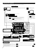
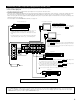
Connecting a video component equipped with S-Video jacks
• When making connections, also refer to the operating instructions of the other components.
• A note on the S input jacks
The input selectors for the S inputs and pin jack inputs work in conjunction with each other.
• Precaution when using S-jacks
This unit’s S-jacks (input and output) and video pin jacks (input and output) have independent circuit structures, so that video signals input from
the S-jacks are only output from the S-jack outputs and video signals input from the pin jacks are only output from the pin jack outputs.
When connecting this unit with equipment that is equipped with S-jacks, keep the above point in mind and make connections according to the
equipment’s instruction manuals.
For a description of the MONITOR OUT terminals, see page 10.
SPEAKER SYSTEMS
ANTENNA TERMINALS
MULTI
ZONE 2
SURR.-B
SURR.-A
CENTER
CONPONENT VIDEO
FRONT
SURR.
BACK
R
R
R
R
R
IN
DVD
Y
VDP TV DBS /
V. AUX VCR-1 VCR-2 VCR-3 VCR-1 VCR-2 VCR-3
12SAT1
VIDEO
S-VIDEO
OUT
OUT OUT
IN
MONITOR
DVD
MULTI ZONE
IN
TV
Y
IN
DBS / SAT
Y
OUT
MONITOR
P
B
/C
B
P
R
/C
R
P
B
/C
B
P
R
/C
R
P
B
/C
B
P
R
/C
R
P
B
/C
B
P
R
/C
R
Y
AM
LOOP
FMCOAX.
75Ω
ANT.
OUT
S-VIDEO
IN
S-VIDEO
OUT
S-VIDEO
IN OUT
S-VIDEO
IN OUT
S-VIDEO
LD player, CDV player, etc.
Monitor TV
Video deck 2
Video deck 1
TV or satellite broadcast tuner
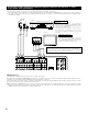
Connecting a video disc player (VDP)
Connecting a monitor TV
Connecting the video decks
Connecting a TV/DBS tuner
VDP
• Connect the video disc player’s S-Video output jack to the
S-VIDEO VDP IN jack using an S-Video connection cord.
• A DVD player can be connected to the DVD jacks in the same
way.
• It is also possible to connect a video disc player, DVD player,
video camcorder, game machine, etc., to the V.AUX jacks.
MONITOR OUT
• Connect the TV’s or DBS tuner’s S video input (S-VIDEO INPUT)
to the MONITOR OUT-1 jack using a S jack connection
cord.
• The monitor TV can also be connected in the same way to the S-
VIDEO MONITOR OUT-2 jack.
S-VIDEO
• Connect the TV’s or DBS tuner’s S video output jack
(S-VIDEO OUTPUT) to the TV/DBS IN
jack using an S jack connection cord.
S-VIDEO
• Connect the video deck’s S output jack (S-OUT) to the VCR-1 IN jack and
the video deck’s S input jack (S-IN) to the
VCR-1 OUT jack using S jack connection cords.
• Connect the video deck’s S output jack (S-OUT) to the VCR-2 IN jack and
the video deck’s S input jack (S-IN) to the
VCR-2 OUT jack using S jack connection cords.
Connect the third video deck to the VCR-3 jacks in the same way.
S-VIDEO
S-VIDEO
S-VIDEO
S-VIDEO
Connect the components’ audio inputs and outputs as described on page 7.
NOTE:
• The MONITOR OUT-2 output switches together with the input function selected with the REC/M-ZONE 2 button. To use as the monitor
output, set “SOURCE” as the REC/M-ZONE 2 input function. At this time, the on-screen display signals are output from the video signal
MONITOR OUT-2 (yellow) or S-Video signal MONITOR OUT-2 jack.