AV SURROUND RECEIVER AVR-987 OPERATING INSTRUCTIONS
SAFETY INSTRUCTIONS 2 SAFETY PRECAUTIONS CAUTION RISK OF ELECTRIC SHOCK DO NOT OPEN CAUTION: TO REDUCE THE RISK OF ELECTRIC SHOCK, DO NOT REMOVE COVER (OR BACK). NO USER-SERVICEABLE PARTS INSIDE. REFER SERVICING TO QUALIFIED SERVICE PERSONNEL.
FCC INFORMATION (For US customers) 2 NOTE ON USE / OBSERVATIONS RELATIVES A L’UTILISATION 1. PRODUCT This product complies with Part 15 of the FCC Rules. Operation is subject to the following two conditions: (1) this product may not cause harmful interference, and (2) this product must accept any interference received, including interference that may cause undesired operation. 2.
2 We greatly appreciate your purchase of the AVR-987. 2 To be sure you take maximum advantage of all the features the AVR-987 has to offer, read these instructions carefully and use the set properly. Be sure to keep this manual for future reference should any questions or problems arise. “SERIAL NO.
Getting Started Getting Started Thank you for choosing the DENON AVR-987 AV Surround Receiver. This remarkable component has been engineered to provide superb surround sound listening with home theater sources such as DVD, as well as providing outstanding high fidelity reproduction of your favorite music sources. As this product is provided with an immense array of features, we recommend that before you begin hookup and operation that you review the contents of this manual before proceeding.
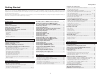
Getting Started Getting Started Advanced Setup – Part 1 Operating the remote control unit System setup items and default values·····················43 ~ 45 Navigating through the System Setup Menu····················46 About the display··································································46 Audio Input Setup Setting the Digital In Assignment·········································47 Setting the EXT.
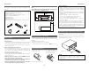
Getting Started Getting Started Accessories Cautions on installation Check that the following parts are attached in addition to the main unit: Note: For heat dispersal, do not install this unit in a confined space such as a bookcase or similar enclosure. q Operating instructions ......................................................1 w Warranty (for North America model only) .............................1 e Service station list.............................................................
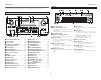
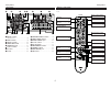
Getting Started Getting Started Part names and functions Display For details on the functions of these parts, refer to the pages given in parentheses ( ). !3 !2 !1 !0 o iu y Front panel !4 !3 !2 !1 !0 o i q w !9 !5 !6 @0@1 @22 @ @1 @ @33 @4 @5 @6 @ @77 @8 @9 #0 q Input signal indicator w Input signal channel indicator !7 !8 • The audio channel(s) included in the input signal light(s). • This lights when the digital signal is inputted.
Getting Started Getting Started Rear panel !5 !4 Remote control unit !3 !2 !1 !0 o To operate the AVR-987, use the mode selector switches to select “TAPE” “CD-R/MD” or “CD”, mode.
Getting Started Rear ZOOM2 buttons ···································(41) Easy Setup Procedure • This section contains the basic steps necessary to configure the AVR-987 according to your listening room environment and the source equipment and loudspeakers you are using. • To set the sound field manually, see pages 56 ~59. ZOOM1 (MAIN) buttons ···································(41) Easy to setup flow Placing the speakers.
Easy Setup Procedure Easy Setup Procedure 2 Connections Speaker connections Connect the speaker terminals with the speakers making sure that like polarities are matched (< with <, > with >). NOTE: When making connections, take care that none of the individual conductors of the speaker cable come in contact with adjacent terminals, with other speaker cable conductors, or with the rear panel and screws. NEVER touch the speaker terminals when the power is on. Doing so could result in electric shocks.
Easy Setup Procedure Easy Setup Procedure • For best picture quality (especially with progressive DVD and other high definition sources), choose the component video or HDMI connection to your monitor. S-Video and composite video outputs are also provided if your monitor does not have component video inputs. Connecting a DVD player and monitor • To connect the video output from the DVD player to the AVR-987, you only need to choose one connection type.
Easy Setup Procedure Easy Setup Procedure ENTER SYSTEM SETUP DHFG [OFF] [ON] Auto Setup/Room Equalizer (Room EQ) Functions • The AVR-987’s auto setup and room equalizer functions use the attached microphone to measure the acoustic properties in the room and automatically make the optimum settings. • The optimum listening environment at all listening positions in the home theater is achieved so multiple listeners can enjoy listening at the same time.
Easy Setup Procedure w Before performing the Auto Setup procedure 1 Turn on your subwoofer. Set the volume to halfway and set the crossover frequency to the maximum or Low pass filter off if your subwoofer can adjust the output volume and the crossover frequency. Some subwoofers have a standby mode. Be sure to turn this function off before performing the Auto Setup procedure. 2 Turn on your monitor. 3 Press . Easy Setup Procedure e Perform the Auto Setup procedure 1 Press SYSTEM SETUP.
Easy Setup Procedure Easy Setup Procedure y Preliminary measurements This procedure is used to automatically determine the background noise, whether or not speakers are connected, and the polarities of the connected speakers. 1 Press D H to select “Start”, then press F. • The preliminary measurements start. D H to select “Speaker Detect Check”, then 2 Press press ENTER. 3 Cautions during measurements: • Loud test tones are output during the measurements.
Easy Setup Procedure Easy Setup Procedure i Checking and storing the measurement results The measurement results displayed at “u Speaker measurements” can be checked and stored in the memory. 1 Press D H to select the item, then press ENTER. Error messages An error message is displayed if the measurements could not be completed automatically due to the speaker layout, the measuring environment, etc. Please check the following matters, reset the pertinent items, and measure again.
Connecting Other Sources NOTE: • Do not plug in the power supply cord until all connections have been completed. • When making connections, also refer to the operating instructions of the other components. • Be sure to connect the left and right channels properly (left with left, right with right). • Do not bundle power cords together with speaker cables. Doing so could result in humming or noise.
Connecting Other Sources Connecting Other Sources The video conversion function • Even if the formats of the video signals from the various players differ, the different formats can be converted and the signals output to the monitor from a single video output terminal. We recommend outputting with the format offering the highest quality video signals possible. • With analog video signal connections, generally quality is higher in the order shown below.
Connecting Other Sources Video convert S-VIDEO MONITOR OUT OFF – – – Used Not used – – – Used Not used – – – Used Not used – – – Used Not used HDMI E E E E E E E E E E C C C C C C C C C C Connecting Other Sources Input signals COMPONENT S-VIDEO E E E E C E C E C E C E E C C C C C C C E E E E E C E C E C C E C E C C C C C C C : Signal input E : No signal VIDEO E C E C C E C E C C E C E C C E C E C C HDMI E E E E E E E E E E HDMI HDMI HDMI HDMI HDMI HDMI HDMI HDMI HDMI HDMI MONITOR OUT COMPONENT S-VI
Connecting Other Sources Connecting Other Sources Connecting equipment with HDMI terminals [To convert analog video signals to HDMI signals] Connecting a TV tuner • For best picture quality choose the component video connection to your TV tuner. S-Video and composite video outputs are also provided if your TV tuner does not have component video inputs. • To connect the digital audio output from the TV tuner, you can choose from either the coaxial or the optical connections.
Connecting Other Sources Connecting Other Sources Connecting the external inputs (EXT. IN) terminals Connecting a CD player To connect the digital audio output from the CD player, you can choose from either the coaxial or optical connections. If you choose to use the optical connection, it needs to be assigned. For more information about Digital Input Assignment ( page 47).
Connecting Other Sources Connecting Other Sources Connecting a DVD recorder Connecting a VCR • For best picture quality choose the component video connection to your DVD recorder. S-Video and composite video outputs are also provided. If you choose to use the component video connection, it needs to be assigned. For more information about Component Input Assignment ( page 50).
Connecting Other Sources Connecting Other Sources Input signals LINEAR PCM DVD-Video Dolby Digital DTS LINEAR PCM PACKED PCM DVD-Audio (with CPPM / without CPPM) CD LINEAR PCM Multi area Super Audio Stereo area CD CD area Connecting a CD recorder or MD recorder If you wish to perform analog dubbing from a digital source, such as a CD or MD recorder to an analog recorder such as a cassette deck, you will need to connect the analog inputs and outputs as shown below, in addition to the digital audio connecti
Connecting Other Sources Connecting Other Sources Connecting the antenna terminals Connecting the XM terminal • AVR-987 is the XM Ready® receiver. You can receive XM Satellite Radio® by connecting to the XM Connect-and-PlayTM (sold separately) and subscribing the XM service. • Plug the XM Connect-and-Play antenna into XM connector on the rear panel. • Position the XM Connect-and-Play antenna near a south-facing window to receive the best signal. For details, see “XM Satellite Radio” ( page 36, 37).
Connecting Other Sources Connecting Other Sources Connecting the iPod® Connecting the TRIGGER OUT jacks When using an iPod, you must Connect the DENON original Control Dock for iPod and the DOCK CONTROL jack on the AVR-987 with a mini-jack and assign the iPod to any AUDIO and/or S-VIDEO terminal(s). The diagram below shows an example of connections for when the iPod is assigned to the VDP terminal.
Connecting Other Sources Connecting Other Sources ZONE2 speaker out connections Connecting the PRE OUT terminals • When the surround back’s power amplifier is assigned to the ZONE2 output channel at “Power Amp Assign” in the “System Setup Menu”, the surround back speaker terminals can be used as the ZONE2 speaker out terminals ( page 54). • The connections diagram below is an example for when the surround back speaker is assigned to the ZONE2 stereo 2 channel.
Basic Operation Basic Operation FUNCTION Playing the input source SURROUND PARAMETER 1 4 Use VOLUME to adjust the volume. Use FUNCTION to select the input source you want to play. To select the input source when ZONE2/REC SELECT, VIDEO SELECT or TUNING PRESET is selected, press then operate . 2 Press INPUT MODE. AUTO INPUT MODE VOLUME FUNCTION VOLUME PCM EXT. IN DTS ANALOG Press to select “ANALOG”, to select “EXT. IN”.
Basic Operation Basic Operation PURE DIRECT ROOM EQ Selecting the room equalizer mode The room equalizer function offers 3 correction curves: “Audyssey”, “Front” and “Flat”. These modes can be selected after performing the auto setup procedure. Switching the front speakers Press [SPEAKER]. FRONT A Press ROOM EQ. OFF Audyssey Front Flat Manual • The “MultEQ XT” indicator lights green when “Audyssey” is selected, red when “Front” or “Flat” is selected.
Basic Operation Using the surround modes Types of surround modes and their features The AVR-987 is equipped with many surround modes. We recommend using the surround modes as described below in order to achieve the maximum effect for the specific signal source. is a 6.1-channel/7.1-channel surround mode. Sources recorded in Dolby Digital EX DOLBY DIGITAL EX / +PLIIx* ( page 26) • This mode is optimized for playing sources recorded in Dolby Digital EX. Sources recorded in DTS-ES DTS-ES DSCRT 6.1 / MTRX 6.
Basic Operation Basic Operation ENTER SURROUND STANDARD PARAMETER Selecting the Dolby Digital and DTS Surround mode (only with digital input) an input source for which digital (COAXIAL, 1 Select OPTICAL etc.) is set ( page 47 or 49 ~ 50). INPUT MODE DHFG 2 Press INPUT MODE to select “AUTO”. 3 Press STANDARD to select “STANDARD”. a program source with the , 4 Play mark. •“ ” or “ ” lights, depending on the source. 5 Press SURROUND PARAMETER.
Basic Operation Basic Operation AFDM (Auto Flag Detect Mode): • ON: When software including Dolby Digital EX or DTS-ES 6.1channel identification signals is played, 6.1-channel playback is performed automatically. The surround mode is set according to the program source being played. The “SB CH OUT” parameter on the surround parameters screen cannot be selected. • OFF: Not detected automatically. The surround mode can be selected freely.
Basic Operation Basic Operation ENTER SURROUND STANDARD PARAMETER Selecting the DTS NEO:6 mode It is possible to play analog input signals and digital input signals (2-channels) in the surround mode. 1 Press STANDARD to select “DTS NEO:6”. DOLBY PLIIx DTS NEO:6 2 Play a program source. 3 Press SURROUND PARAMETER. 4 Press F G to select the play mode. DHFG CINEMA: This mode is optimum for playing movies.
Basic Operation Basic Operation Surround modes and parameters Signals and adjustability in the different modes Parameter (default values are shown in parentheses) Channel output Surround Mode PURE DIRECT, DIRECT MULTI CH DIRECT STEREO EXT. IN MULTI CH IN WIDE SCREEN DOLBY PRO LOGIC IIx DOLBY PRO LOGIC II DTS NEO:6 DOLBY DIGITAL DTS SURROUND 7CH STEREO SUPER STADIUM ROCK ARENA JAZZ CLUB CLASSIC CONCERT MONO MOVIE VIDEO GAME MATRIX VIRTUAL SURROUND FRONT SURROUND SUB- D.
Basic Operation Basic Operation 2 Differences in surround mode names depending on the input signals Input signals Button DTS Surround Mode Note ANALOG LINEAR PCM *1 *1 E E E E E E E C C STANDARD DTS SURROUND DTS ES DSCRT6.1 DTS ES MTRX6.
Basic Operation Basic Operation Button Input signals DTS Surround Mode DIRECT DIRECT MULTI CH DIRECT M DIRECT + PLIIx CINEMA M DIRECT + PLIIx MUSIC PURE DIRECT PURE DIRECT MULTI CH PURE DIRECT M PURE D + PLIIx CINEMA M PURE D + PLIIx MUSIC DSP SIMULATION 7CH STEREO WIDE SCREEN SUPER STADIUM ROCK ARENA JAZZ CLUB CLASSIC CONCERT MONO MOVIE VIDEO GAME MATRIX VIRTUAL STEREO STEREO Note ANALOG LINEAR PCM *2 *1 C E E E *2 *1 *3 DOLBY DIGITAL DOLBY DIGITAL DOLBY EX DIGITAL (With no Flag) (5.
Basic Operation Basic Operation Using the DENON original surround modes The AVR-987 is equipped with a high performance digital signal processor (DSP) that uses digital signal processing to recreate sound fields artificially. One of 10 surround modes can be selected according to the program source and parameters can be further adjusted to achieve even more realistic sound fields. Types of surround modes and their features 7CH STEREO (NOTE 1) This mode lets you enjoy stereo sound with 7 speakers.
Basic Operation DSP SIMULATION Basic Operation ENTER SURROUND PARAMETER Selecting the DSP surround simulation 1 Press [DSP SIMULATION]. 7CH STEREO SUPER STADIUM VIRTUAL ROCK ARENA MATRIX JAZZ CLUB VIDEO GAME <7CH STEREO> DHFG WIDE SCREEN MONO MOVIE 2 Press SURROUND PARAMETER. Press D H to select the item, then press F G to 3 set. EFFECT: (WIDE SCREEN mode only) Effect signals with the multi-surround speaker effects are played.
Basic Operation Basic Operation CH SEL/ ENTER SURROUND PARAMETER Setting the tone control Adjust the bass and treble to suit your tastes. 2 Adjusting the tone 1 Press SURROUND PARAMETER. 2 Press D H to select “TONE”, then press F. In the direct mode, “TONE” cannot be selected. DHFG [SHIFT] [CHANNEL] 3 Press G to select “OFF”. D H to select “Bass” or “Treble”, then press 4 Press F G to set the level. Can be adjusted within the range of –6 dB to +6 dB. 5 Press ENTER.
Basic Operation Basic Operation Using the fader function With this function, the volume of all the front side speakers or all the rear side speakers can be adjusted (attenuated) at once. 1 Press CH SEL/ENTER. 2 Press D H or CH SEL/ENTER to select “Fader”. F to attenuate the volume of all the front 3 Press side speakers, G to attenuate the volume of all the rear side speakers. The fader function does not affect the subwoofer.
Basic Operation Basic Operation Checking the preset stations Press [ON SCREEN] repeatedly until the “Tuner Preset Stations” screen appears on the OSD. XM Satellite Radio AVR-987 is the XM Ready® receiver. You can receive XM Satellite Radio® by connecting to the XM Connect-and-PlayTM (sold separately) and subscribing the XM service. 2 Introducing XM Satellite Radio There’s a world of audio listening pleasure beyond AM and FM. XM Satellite Radio.
Basic Operation Basic Operation Checking the XM signal strength and Radio ID 1 Either turn or press [TUNER] to select “TUNER”. 2 Press [BAND] to select “XM”. 3 Press until “SIGNAL” is displayed. • The display changes as shown below according to the receiving condition. Display Condition GOOD Signal strength is good MARGINAL Signal strength is marginal WEAK Signal strength is poor NO Loss of the signal the RADIO 1 2 Press [BAND] to select “XM”.
Advanced Operation NIGHT ENTER Advanced Operation Night mode The night mode can be set when playing Dolby Digital sources. The dialogues are easier to hear at night and when listening with the volume low. Press NIGHT. Combining the currently playing sound with the desired image (VIDEO SELECT function) Press
Advanced Operation Advanced Operation Playing the iPod® Listening to music The music recorded on the iPod can be played when using a DENON original Control Dock for iPod (ASD-1R). The iPod can be controlled using the buttons on the main unit and the remote control unit. iPod is a trademark of Apple Computer, Inc., registered in the U.S. and other countries. 1 Press D H to select the music file, then press ENTER or G. Press F to return to the music menu screen. 2 Press ENTER or G. • Playback starts.
Advanced Operation Advanced Operation Multi zone music entertainment system Multi-zone playback using the SPEAKER terminals • When the outputs of the ZONE2 output terminals are wired and connected to power amplifiers installed in other rooms, different sources can be played in rooms other than the MAIN ZONE in which this unit and the playback devices are installed. (Refer to ZONE2 on the diagram below.
Advanced Operation Advanced Operation Outputting a program source to amplifier, etc., in the ZONE2 room (ZONE2 SELECT mode) FUNCTION 1 Press to display the “ZONE2 SOURCE” on the display. • The “ Remote control unit operations during multisource playback 1 Set [MODE1] to “AUDIO”. ” indicator lights. RECOUT ZONE2 Set [MODE2] to “ZONE2”. “ZONE2 SOURCE” displayed, turn 2 2 With to select the source you want to output appears on the display.
Advanced Operation Advanced Operation Recording (audio and/or video) until “RECOUT” 1 Press appears on the display. RECOUT ZONE2 Use to select the source to be 2 recorded (audio and/or video). • The “ ” indicator lights. 3 Record (the audio or video signals). For operations, see the operating instructions of the device from which you are recording (audio or video signals).
Advanced Setup – Part 1 Advanced Setup – Part 1 System setup items and default values 1. Auto Setup/Room EQ Default settings Page 1 Auto Setup This unit performs an analysis of the speaker system and measures the acoustic characteristics of your room to permit an appropriate automatic setting. Items – 9 ~ 12 Room EQ Setup Set the Room Equalizer setting with “All” or “Assign” for each surround mode.
Advanced Setup – Part 1 Advanced Setup – Part 1 3. Audio Input Setup Items 1 Digital In Assign Default settings This assigns the digital input terminals for the different input sources. Input source Digital Inputs CD DVD COAX 1 COAX 2 Page VDP TV DBS VCR-1 VCR-2 CD-R / TAPE OPT 1 OFF OPT 2 OPT 3 OFF OPT 4 V.AUX OPT 5 47 EXT. IN 2 Subwoofer Level Sets the playback level of the analog signal that was input to the EXT. IN subwoofer terminal.
Advanced Setup – Part 1 Advanced Setup – Part 1 5. Advanced Playback Items Default settings Page Make the 2-channel direct mode and stereo mode speaker 2ch 1 Direct/Stereo settings. Basic 52 Dolby Digital 2 Setup Turn the audio compression on or off when down-mixing Dolby Digital signals. OFF 53 Auto 3 Surround Mode Set whether or not to store the surround mode last played for the input signal.
Advanced Setup – Part 1 Advanced Setup – Part 1 Navigating through the System Setup Menu ENTER In addition to the easily understandable on screen display, the AVR-987 is also equipped with displays for checking the settings. Use this when making settings and operating. Below are some examples of typical displays. 1 Press SYSTEM SETUP. • The “System Setup Menu” appears. D H to select the item you want to set, then 2 Press press ENTER.
Advanced Setup – Part 1 Advanced Setup – Part 1 Audio Input Setup Setting the EXT. IN Subwoofer Level Setting the Digital In Assignment This assigns the digital input terminals for the different input sources. D H to select “Audio Input Setup”, then 1 Press press ENTER. Press D H to select “Digital In Assign”, then press 2 ENTER . D H to select the input source, then press F 3 Press G to set. Sets the playback level of the analog signal that was input to the EXT. IN subwoofer terminal.
Advanced Setup – Part 1 Advanced Setup – Part 1 Setting the Input Function Level The playback level is corrected individually for the different input sources. Setting the Function Rename The name of the input function that is displayed can be changed. Setting the Tuner Presets 2 Auto Preset Memory Up to 56 FM stations can be preset automatically. D H to select “Input Function Lev.”, then 1 D H to select “Tuner Presets”, then press 1 Press 1 Press press ENTER. ENTER.
Advanced Setup – Part 1 Advanced Setup – Part 1 2 Preset Skip 2 Preset Name Preset channels that are not used often can be skipped. The preset channels can be given the names you want. (Except the XM channels.) Video Setup D H to select “Preset Skip”, then press 1 Press D H to select “Preset Name”, then press ENTER. 1 Press ENTER. D H to select the preset channel, then press 2 Press F G to set. 2 Press D H to select the preset channel, then press F G to set.
Advanced Setup – Part 1 1 4 Advanced Setup – Part 1 Setting the Component In Assignment 2 3 5 This assigns the component video input terminals for the different input sources. 1 Press D H to select “Component In Assign”, then press ENTER. 2 Press D H to select the input source, then press F G to set. 1-RCA, 2-RCA, 3-RCA: Assign the “1-RCA” (or “2-RCA” or “3-RCA”) input terminal to the input function.
Advanced Setup – Part 1 Setting the HDMI Out Setup Set whether or not to up-convert from analog video signals to HDMI. When this function is used, the format of the signal output from the HDMI terminal can be set. Advanced Setup – Part 1 1 Setting the Audio Delay 2 D H to select “Audio Delay”, then press 1 Press ENTER. D H to select “HDMI Out Setup”, then 1 Press press ENTER. D H to select the item, then press F G to 2 Press set.
Advanced Setup – Part 1 Advanced Setup – Part 1 Setting the On Screen Display (OSD) Set whether or not to display the on screen display for indications other than the menu screens. D H to select “On Screen Display”, then 1 Press press ENTER. 2 Press D H to select the item, then press F G to set. Function/Mode Status: • ON, OFF: Select “ON” to display the on screen display when the input source is selected, “OFF” if you do not want to display it.
Advanced Setup – Part 1 Advanced Setup – Part 1 Setting the Dolby Digital Downmix Option Setup Turn the audio compression on or off when down-mixing Dolby Digital signals. 1 Press D H to select “Dolby Digital Setup”, then press ENTER. 2 Press F G to set. ON: The dynamic range is compressed automatically according to the combination of speakers being used. Set “Compression” to “ON” if it seems that sound is distorted because the input level exceeds the allowable input for the front speakers.
Advanced Setup – Part 1 1 Advanced Setup – Part 1 1 Option Setup 2 2 Setting the Power Amplifier Assignment 3 To suit your preference, a surround back channel’s power amplifier can be assigned to the front channel (“Front A” or “Front B”) for bi-amp playback, ZONE2. 3 4 D H to select “Option Setup”, then press 1 Press ENTER. Press D H to select “Power Amp Assign”, then 2 press ENTER. 3 Press F G to set. • “Base Curve Copy” is displayed after performing the Auto Setup.
Advanced Setup – Part 1 Setting the Volume Control This sets the volume level of output. Advanced Setup – Part 1 1 2 D H to select the input source, then press F 4 Press G to set. Press D H to select “Volume Control”, then press ENTER. ON, OFF: When that input source is selected, the power supplied from the trigger out jack turns on (or off). D H to select the item, then press F G to 2 Press set. “MAIN” was selected at step 3: 5 When Press D H to select the surround mode, then 1 Vol.
Advanced Setup – Part 1 Setting the Setup Lock This sets whether or not to lock the system setup settings so that they cannot be changed. D H to select “Setup Lock”, then press 1 Press ENTER. 2 Press F to select “ON”, then press ENTER. 1 Advanced Setup – Part 2 Speaker Setup Setting the Speaker Configuration • If the “Auto Setup” procedure has already been performed, there is no need to make this setting. • Perform this setting if you wish to make the settings for your speaker systems manually.
Advanced Setup – Part 2 1 Advanced Setup – Part 2 Setting the Subwoofer Setup 2 Select the method of playback of the subwoofer for playing the low bass signals. 3 D H to select “Subwoofer Setup”, then 1 Press press ENTER.
Advanced Setup – Part 2 Advanced Setup – Part 2 D H to select the speaker, then press F G 3 Press to set. 4 1 Press ENTER. 1 Setting the Channel Level Set the volume of the various speakers so that the sound output from the speakers and the subwoofer seems to have the same volume level. 2 3 D H to select “Channel Level”, then press 1 Press ENTER. 2 2 Press F G to set. 4 -1 Auto: Adjust the level while listening to the test tones produced automatically from each speaker.
Advanced Setup – Part 2 Advanced Setup – Part 2 2 Adjusting the test tone using the remote control unit Adjustment of the test tones using the remote control unit is only possible in the “Auto” mode and only valid in the STANDARD (Dolby Surround and DTS Surround) mode. The adjusted levels are automatically stored for the different surround modes. 1 1 2 F G to select “Advanced” 1 Press “Crossover Frequency” screen. • Test tones are output from the different speakers.
Advanced Setup – Part 2 Others Setup Setting the Room Equalizer Setup Advanced Setup – Part 2 1 Setting the Direct Mode Setup 2 3 Set the Room Equalizer setting with “All” or “Assign” for each surround mode. Press D H to select “Direct Mode Setup”, then 1 press ENTER. D H to select “Room EQ Setup”, then press 1 Press ENTER. 2 Press F G to set, then press ENTER. All: Sets the equalizer for all surround modes. Assign: Sets the equalizer individually for each surround mode ( page 24).
Advanced Setup – Part 2 Advanced Setup – Part 2 Setting the MIC Input Select Sets whether the setup microphone is connected to the pin jack (V. AUX L channel) or mini jack (SETUP MIC). Check the parameter 1 Press D H to select “Parameter Check”, then press ENTER. D H to select “Mic Input Select”, then press 1 Press ENTER. 2 Press D H to select the item, then press ENTER. 2 Press F G to set. D H to select “EQ Parameter Check”, then 3 Press press ENTER.
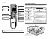
Operating the remote control unit Operating the remote control unit Operating DENON audio components 1 Set [MODE1] to “AUDIO”. 2 Set [MODE2] to the position for the component to be operated (CD, CD-R/MD or TAPE). 2 Set [MODE2] to the component to be registered. Press [ZONE2 OFF] and [ZONE1 (MAIN) ON] at 3 the same time. • The indicator starts flashing. to the included list of preset codes, 4 Referring press [NUMBER] to input the preset code (a 3[MODE1] [MODE2] 3 Operate the audio component.
Operating the remote control unit OFF SHIFT Operating the remote control unit ON/SOURCE CHANNEL+, – Operating a component stored in the preset memory 1 Set [MODE1] to “AUDIO” or “VIDEO”. 1, 2, 3, A/B, 0, SKIP+, 6 7, 8 9, VCR CHANNEL + – SETUP DHFG DISPLAY MODE1 ENTER AUDIO RETURN MENU MODE2 Set to the AUDIO side for the CD, TAPE or CD-R/MD position, and to the VIDEO side for the DVD/VDP, DBS/CABLE, VCR or TV position. [MODE2] to the component you want to 2 Set operate. 3 Operate the component.
Operating the remote control unit Operating the remote control unit 2 Functions of buttons for the different devices CD player CD recorder or MD recorder MODE2 CD CD-R / MD TAPE OFF – – – Power OFF – ON / SOURCE – – – Power on/Standby Power on/Standby SHIFT – – – – – – – – CHANNEL + – – – – – – Station selection Channel selection Channel selection Device operated MODE1 Front DVD player Video disc player Satellite tuner or Cable TV TV (Monitor) VCR DBS / CABLE TV
Operating the remote control unit Operating the remote control unit Setting the punch through function “Punch Through” is a function allowing you to operate the PLAY, STOP, MANUAL SEARCH and AUTO SEARCH on CD, TAPE, CDR/MD, DVD/VDP or VCR components when in the DBS/CABLE or TV mode. By default, nothing is set. 1 Set [MODE1] to “VIDEO”. [MODE2] to the component to be registered 2 Set (DBS/CABLE or TV). [MODE1] [MODE2] 3 Press [MEMORY] and [INPUT] at the same time. •The indicator starts flashing.
Additional Information Additional Information w When playing movies and musics About the speakers 2 Number of surround back speakers Surround back speakers We recommend using 2 speakers. When using dipolar speakers in particular, be sure to use 2 speakers. Sound position directly to the rear can be achieved easily by adding a surround back speaker to a 5.1-channel system.
Additional Information Surround The AVR-987 is equipped with a digital signal processing circuit that lets you play program sources in the surround mode to achieve the same sense of presence as in a movie theater. Dolby Surround [1] Dolby Digital Dolby Digital is the multi-channel digital signal format developed by Dolby Laboratories. A total of 5.1-channels are played: 3 front channels (“FL”, “FR” and “C”), 2 surround channels (“SL” and “SR”) and the “LFE” channel for low frequencies.
Additional Information Audyssey MultEQ XT Audyssey MultEQ XT is a technology designed to provide the optimum listening environment for multiple listeners within the listening area. Test data collected from multiple listening points is analyzed comprehensively and equalization that improves the sound quality for the entire listening area is performed. Audyssey MultEQ XT not only corrects frequency response problems in large listening areas, it also fully automates the surround system setup.
Troubleshooting Symptom Troubleshooting No test tones produced. If a problem should arise, first check the following. 1. Are the connections correct? 2. Have you operated the receiver according to the Operating Instructions? 3. Are the speakers and other components operating properly? If this unit is not operating properly, check the items listed in the table below. Should the problem persist, there may be a malfunction. Disconnect the power immediately and contact your store of purchase.
Troubleshooting Specifications Symptom Cause “NO SIGNAL” is • The signal cannot be received. displayed in the XM mode. “OFF AIR” is displayed in the XM mode. Receiving only channels 0 and 1. Measures Page • Reposition your XM Connect-andPlay antenna. 37 • The selected channel is not • Select the another channel. currently broadcasting. XM • The XM Tuner is not activated. • Contact XM Radio.
2 List of preset codes DVD Audio Dynamic 005, 085 Denon 014, *[111] Audiovox 088 Aiwa 009 Beaumark 087 Jensen Hitachi 010 Broksonic 086, 093 JVC JVC 006, 011 Calix 088 Konka 012, 013 Candle 006, 087, 088, 089, 090 Magnavox 005 Canon 049, 057 Mitsubishi 004 Capehart 025, 055, 056, 071 Kodak 088 Panasonic 014 Carver 015 Lloyd 009, 094 Philips 005, 015, 016, 017 CCE 095 LXI 088 Pioneer 003, 008 Citizen 006, 007, 087, 088, 089, 090, 095 Magnavox 015, 016, 042
Optonica 021 Sylvania 009, 015, 016, 017, 041, 049, 094 Bauer 155 Panasonic 024, 049, 064, 066, 067, 068, 069, 107 Symphonic 009, 094 Belcor 047 Perdio 009 Tandy 009 Bell & Howell 045, 118 Pentax 009, 013, 023, 058, 090 Tashiko 009, 088 Bradford 061 Philco 015, 016, 049 Tatung 004, 026, 030 Brockwood 003, 047 Philips 015, 021, 042, 049, 105 Teac 004, 009, 026, 094 Candle Pilot 088 Technics 024, 049 Pioneer 005, 013, 029, 036, 037, 038, 045, 085 Teknika 009, 010, 022
Futuretech 004 Minutz 066 SBR 015 GE 020, 036, 037, 040, 044, 058, 066, 088, Mitsubishi 001, 016, 039, 048, 056, 057, 058, 065, Schneider 015 119, 120, 125, 147 081, 082, 083, 105 Scott 062 000, 015, 029, 031, 039, 048, 051, 056, Montgomery Ward 011, 020, 144, 145, 146 Sears 008, 014, 021, 022, 023, 024, 025, 040, 057, 067, 068, 069, 116 Motorola 121, 147 Grundy 062 MTC 031, 034, 039, 048, 095 Hitachi 029, 031, 051, 052, 070, 111, 112, 113, NAD 008, 075, 076, 128 124, *[134]
CABLE DBS (SATELLITE) Emerson 004, 005, 006, 007 ABC 006, *[007], 008, 009 Alphastar 054 Fisher 003, 008, 009, 010 Archer 010, 011 Chaparral 035, 036 JVC 018, 019 Century 011 Dishnet 053 Kenwood 011, 012, 013, 014, 017 Citizen 011 Drake 037, 038 Magnavox 006, 015, 035 Colour Voice 012, 013 Echostar Dish 062, 066 Marantz 016, 028, 035 016, 024 Comtronic 014 GE 048, 055, 056 MCS Eastern 015 General Instruments 039, 040, 041 Onkyo 025, 027 Garrard 011 Grundig 070
Magnavox 002 Marantz 002 Onkyo 016, 018 Optimus 007, 008 Panasonic 012 Philips 002 Pioneer 007, 008, 009 Sony 013, 014, 015 Technics 012 Victor 004 Wards 007 Yamaha 010, 011 *[ ] : Preset codes set upon shipment from the factory. DVD preset codes B Model No.
TOKYO, JAPAN www.denon.com Denon Brand Company, D&M Holdings Inc.