
User's Manual


71
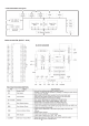
R2A15218FP Terminal Functions
PRELIMINARY
PIN No.
Name
Function
49 DATA
Input pin of control data
50 CLOCK Input pin of control clock
Output pin of FL/FR/C/SW/SL/SR/SBL/SBR channel
FRIN2, FLIN2,
SRN2,SLIN2,
SWIN2,CIN2,
SBRIN2,SBLIN2
43,42,
41,40,
39,38,
37,36
Input pin of L/R/C/SW/SL/SR/SBL/SBR channel (Multi IN 1/2)
Output pin for L/R channel REC Output
Frequency characteristic setting pin of L/R channel tone control (Treble)
28,34
TREL, TRER
26,27,
32,33
23,21,
17,15,
11,9,
5,3
FROUT,FLOUT,
COUT,SWOUT,
SROUT, SLOUT,
SBROUT,SBLOUT
BASSL1,BASSL2
BASSR1,BASSR2
FLIN1, FRIN1,
CIN1,SWIN1,
SLIN1,SRIN1,
SBLIN1,SBRIN1
93,94,
95,96,
97,98,
99,100
Frequency characteristic setting pin of L/R channel tone control (Bass)
24,20,
18,14,
12,8,
6,2
FRC,FLC,
CC,SWC,
SRC,SLC,
SBRC,SBLC
Connects capacitor for reducing click noise of
L/R/C/SW/SL/SR/SBL/SBR channel volume
INL1,INL2, INL3,
INL4,INL5,INL6,
INL7,INL8,INL9
Input pin of L/R channel (Input Selector)
59,61,63,
65,67,69,
71,73,79
INR1,INR2, INR3,
INR4,INR5,INR6,
INR7,INR8,INR9
58,60,62,
64,66,68,
70,72,78
54,55 ADCL, ADCR
Output pin for L/R channel ADC
90,91
4,7,10,16,
19,22,56
AGND
Analog ground of internal circuit
30
AVCC
Positive power supply to internal circuit
48 DGND
Digital ground of internal circuit
52
AVEE
Negative power supply to internal circuit
46,47 SUBL,SUBR
Output pin for L/R channel SUB Output
RECR3,RECL3
51
MUTE
Outside Mute Control PIN
75,76,
81,82,
83,84,
85,86
INRA/RECR1,INLA/RECL1,
INRB/RECR2,INLB/RECL2,
INR10/RECR4,INL10/RECL4,
INR11/RECR5,INL11/RECL5
Input pin of L/R channel (Input Selector)/
Output pin for L/R channel REC Output
N.C.
1,13,25,29,31,
35,53,
57,74,77,80,
87,88,89,92
No Connected PIN
44,45 SBRCIN,SBLCIN
Input pin for SBL/SBR channel Volume