For U.S.A. & Canada model SERVICE MANUAL MODEL Ver. 2 DVD-1200 DVD AUDIO-VIDEO PLAYER 注 意 サービスをおこなう前に、このサービスマニュアルを 必ずお読みください。本機は、火災、感電、けがなど に対する安全性を確保するために、さまざまな配慮を おこなっており、また法的には「電気用品安全法」に もとづき、所定の許可を得て製造されております。 従ってサービスをおこなう際は、これらの安全性が維 持されるよう、このサービスマニュアルに記載されて いる注意事項を必ずお守りください。 ● For purposes of improvement, specifications and design are subject to change without notice.
DVD-1200 2 TABLE OF CONTENTS SPECIFICATIONS . . . . . . . . . . . . . . . . . . . . . . . . . . . . . . . . . . . . . . . . . . . . . . . . . . . . . . . . . . . . . . . . . . . . . . . . . 3 LASER BEAM SAFETY PRECAUTIONS . . . . . . . . . . . . . . . . . . . . . . . . . . . . . . . . . . . . . . . . . . . . . . . . . . . . . . . 4 IMPORTANT SAFETY PRECAUTIONS . . . . . . . . . . . . . . . . . . . . . . . . . . . . . . . . . . . . . . . . . . . . . . . . . . . . . . . . 5 STANDARD NOTES FOR SERVICING. . .
DVD-1200 SPECIFICATIONS ITEM 1. Video Output CONDITIONS 75 ohm load 2. Optical Digital Out UNIT NOMINAL LIMIT Vpp 1.0 ± 0.1 dBm -18 Vrms 2.0 dB 115 3. Audio (PCM) 3-1. Output Level 1kHz 0dB 3-2. S/N 3-3. Freq. Response DVD fs=48kHz 4~22kHz dB ± 0.5 CD fs=44.1kHz 4~20 kHz dB ± 0.5 DVD 1 kHz 0dB % 0.03 CD 1 kHz 0dB % 0.03 3-4. THD+N NOTES: 1. All Items are measured without pre-emphasis unless otherwise specified. 2. Power supply : AC120 V 60 Hz 3. Load imp. : 100 K ohm 4.
DVD-1200 4 LASER BEAM SAFETY PRECAUTIONS This DVD player uses a pickup that emits a laser beam. Do not look directly at the laser beam coming from the pickup or allow it to strike against your skin. The laser beam is emitted from the location shown in the figure. When checking the laser diode, be sure to keep your eyes at least 30cm away from the pickup lens when the diode is turned on. Do not look directly at the laser beam.
DVD-1200 5 IMPORTANT SAFETY PRECAUTIONS Product Safety Notice I. Also check areas surrounding repaired locations. J. Be careful that foreign objects (screws, solder droplets, etc.) do not remain inside the set. Some electrical and mechanical parts have special safety-related characteristics which are often not evident from visual inspection, nor can the protection they give necessarily be obtained by replacing them with components rated for higher voltage, wattage, etc.
DVD-1200 Safety Check after Servicing Examine the area surrounding the repaired location for damage or deterioration. Observe that screws, parts, and wires have been returned to their original positions. Afterwards, do the following tests and confirm the specified values to verify compliance with safety standards. Chassis or Secondary Conductor Primary Circuit Terminals d' 1.
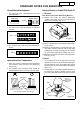
DVD-1200 STANDARD NOTES FOR SERVICING Circuit Board Indications How to Remove / Install Flat Pack-IC 1. The output pin of the 3 pin Regulator ICs is indicated as shown. 1. Removal Top View Out With Hot-Air Flat Pack-IC Desoldering Machine:. (1) Prepare the hot-air flat pack-IC desoldering machine, then apply hot air to the Flat Pack-IC (about 5 to 6 seconds). (Fig. S-1-1) Bottom View In Input 2. For other ICs, pin 1 and every fifth pin are indicated as shown. 5 Pin 1 Fig.
DVD-1200 (4) Bottom of the flat pack-IC is fixed with glue to the CBA; when removing entire flat pack-IC, first apply soldering iron to center of the flat pack-IC and heat up. Then remove (glue will be melted). (Fig. S-1-6) With Soldering Iron: (1) Using desoldering braid, remove the solder from all pins of the flat pack-IC. When you use solder flux which is applied to all pins of the flat pack-IC, you can remove it easily. (Fig.
DVD-1200 Instructions for Handling Semi-conductors 2. Installation (1) Using desoldering braid, remove the solder from the foil of each pin of the flat pack-IC on the CBA so you can install a replacement flat pack-IC more easily. Electrostatic breakdown of the semi-conductors may occur due to a potential difference caused by electrostatic charge during unpacking or repair work. (2) The “I” mark on the flat pack-IC indicates pin 1. (See Fig. S-1-7.
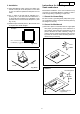
DVD-1200 10 CABINET DISASSEMBLY INSTRUCTIONS 1. Disassembly Flowchart ID/ LOC. No. This flowchart indicates the disassembly steps to gain access to item(s) to be serviced. When reassembling, follow the steps in reverse order. Bend, route, and dress the cables as they were originally.
DVD-1200 To avoid damage of pickup follow these procedures. Insulation Sheet (S-2) 2-1. Disconnect connector (CN301). Remove three screws (S-5) and lift the DVD Mecha. (Fig. D5) 11 (S-2) 2-2. Short the three short lands of FPC cable with solder before removing the FFC cable (CN201) from it. If you disconnect the FFC cable (CN201), the laser diode of pickup will be destroyed. (Fig. D6) [4] Function CBA CAUTION 3: When reassembling, confirm the FFC cable (CN201) is connected completely.
DVD-1200 (S-7) [13] Switch CBA (S-6) [7] Shield Plate (S-11) (S-12) [14] LED CBA [12] AV CBA [8] Progressive CBA Unit [9] DVD Audio CBA Unit CN7102 CN1801 CN1802 (S-8) 12 (S-10) (S-10) Desolder (S-10) (L-7) CN7101 [10] DVD Main CBA Unit CN6001 (S-5) (L-7) (L-5) (L-4) [15] LED CBA Holder CN301 CN201 (S-9) (L-6) (L-5) (L-4) [6] DVD Mecha [11] DVD Main CBA Holder Fig. D7 CN1001 CN1601 Fig.
DVD-1200 HOW TO MANUAL EJECT 1. Remove the Top Case. 2. Rotate the roulette in the direction of the arrow as shown below.
DVD-1200 14 TROUBLESHOOTING FLOW CHART NO.1 The power cannot be turned on. Is the fuse normal? Yes Is normal state restored when once unplugged power cord is plugged again after several seconds? Yes Is the EV +9V line voltage normal? Yes Is each voltage of the secondary side normal? Yes When pressing POWER button (SW2001), is the voltage of 0V supplied to pin(8) of IC2002? Yes Is the voltage of 5V supplied to pin(1) of IC2002? Yes Is the voltage of 3.
DVD-1200 15 FLOW CHART NO.6 P-ON+9V (EV+9V) is not outputted. Is 9V voltage supplied to the emitter of Q1002? No Check D1030, D1048, C1035, C1048, L1009 and the periphery circuit, and service it if defective. Yes No Is the voltage of base on Q1002 lower than the voltage of emitter on Q1002 when turning the power on? Check Q1016 and PWRCON line and service it if defective. Yes Replace Q1002. FLOW CHART NO.7 P-ON+5V is not outputted. (P-ON+9V is outputted normally.
DVD-1200 16 FLOW CHART NO.12 The fluorescent display tube does not light up. Is 5V voltage supplied to Pins(13,43) and Pin(24) of IC6001? Yes Is the voltage of approximately -24V to -28V supplied to Pin(30) of IC6001? Yes No Check the P-ON+5V line and service it if defective. No Check the -FL (-28V) line and service it if defective. No Check R6001, IC6001 and their periphery, and service it if defective.
DVD-1200 17 FLOW CHART NO.14 No operation is possible from the remote control unit. Operation is possible from the DVD, but no operation is possible from the remote control unit.
DVD-1200 FLOW CHART NO.18 [No Disc] indicated. (When the focus servo is not functioning.) Replace the DVD Main CBA. No No improvement can be found. Yes Original DVD Main CBA is poor. Replace the DVD Mecha. FLOW CHART NO.19 [No Disc] indicated. (When the laser beam does not light up.) Replace the DVD Main CBA. No No improvement can be found. Yes Original DVD Main CBA is poor. Replace the DVD Mecha. FLOW CHART NO.20 Both functions of picture and sound do not operate normally.
DVD-1200 A Yes Are the video signals outputted to each pin of IC6102? IC6102 IC6102 IC6102 4PIN 15PIN 14PIN No S-Y Pb/Cb Pr/Cr Is 5V voltage supplied to Pin(16) of IC6102? Yes Replace IC6102. Yes Are the video signals shown above inputted into each pin of IC1402? IC1402 6PIN IC1402 2PIN IC1402 9PIN IC1402 11PIN No Check P-ON+5V line and service it if defective. Check the line between each pin of IC6102 or pin (7) of CN1601, and each pin of IC1402 on the AV CBA, and service it if defective.
DVD-1200 20 FLOW CHART NO.22 Audio is not outputted. (JK6103) Set the disc on the disc tray, and playback. Are the analog audio signals outputted to each pin of CN1601 on AV CBA? No Replace the DVD Main CBA or DVD Mecha. CN1601 11PIN AUDIO-L CN1601 13PIN AUDIO-R Yes Are the analog audio signals inputted to each pin of IC1201. Check each line between each pin of CN1601 and each pin of IC1201 on AV CBA, and service it if defective.
DVD-1200 21 FLOW CHART NO.23 Audio is not outputted. (JK7101) Set the disc (with 5.1ch Audio) on the disc tray, and playback. Are the PCM data signals outputted to each pin of CN7102 on DVD Audio CBA. CN7102 7PIN PCM-DATA0 CN7102 5PIN PCM-DATA1 CN7102 3PIN PCM-DATA2 Yes Are the PCM data signals inputted to each pin of IC7201, IC7202 and IC7203. No No Check each line between each pin of CN7102 and each pin of IC7201,IC7202,IC7203 and service it if defective.
DVD-1200 BLOCK DIAGRAMS System Control/Servo Block Diagram DATA(AUDIO) SIGNAL TRACKING SERVO SIGNAL TO POWER SUPPLY BLOCK DIAGRAM 88 M-MUTE 48 ADAC-ML2 IC451 (CLOCK GENERATOR) 4 1/8 MULTI PLL 15 1/4 PLL2 7 8 X'TAL OSC X451 36.
DVD-1200 Digital Signal Process Block Diagram DATA(VIDEO/AUDIO) SIGNAL DATA(VIDEO) SIGNAL VIDEO SIGNAL DATA(AUDIO) SIGNAL FOCUS SERVO SIGNAL TRACKING SERVO SIGNAL IC102 (SDRAM) ~ ~ DETECTOR C D A B F E CD/DVD CD-LD DVD-LD PD-MONI GND(DVD-PD) GND(CD-PD) GND(LD) ~ 184 205 247 256 ECC SDRAM DATA(0-31) DECODER I/F 124 125 122 123 128 129 126 127 131 130 CN201 6 7 8 5 10 2 9 ~ DSP DECODER STREAM I/F YC7 97 INST.
DVD-1200 Video / Audio Block Diagram DATA(AUDIO) SIGNAL VIDEO SIGNAL AUDIO SIGNAL JK1401 S-VIDEO OUT IC1402 (VIDEO DRIVER) Y WF1 CN601 7 5 3 1 VIDEO-C VIDEO-Y VIDEO-Cb VIDEO-Cr TO DIGITAL SIGNAL PROCESS BLOCK DIAGRAM WF2 6 IC6102 CN1601 7 5 3 1 VIDEO-C VIDEO-Y VIDEO-Cb VIDEO-Cr VIDEO-Y VIDEO-Pb VIDEO-Pr 12 DRIVER WF3 2dB AMP DRIVER 21 2 4dB AMP LPF 2dB AMP DRIVER 23 9 4dB AMP LPF 2dB AMP DRIVER 15 11 4dB AMP LPF 2dB AMP DRIVER 13 15 VIDEO-Pb VIDEO-Cr 2 JK6103 COMPOSIT
DVD-1200 Progressive Block Diagram DATA(VIDEO) SIGNAL IC1803 (PROGRESSIVE ENCODER) 20 ~ FORMATTER DE-INTERLACER FORMATTER 93 94 97 ~ 27 104 40 PLL/CLOCK GENE 42 TEST PATT.GENE.
DVD-1200 DVD Audio Block Diagram DATA(AUDIO) SIGNAL DVD AUDIO CBA IC7201 (AUDIO DAC) IC7101 (SW) 4 1 2 3 SERIAL PORT 4X/8X OVERSAMPLING DIGITAL FILTER /FUNCTION CONTROLLER ENHANCED MULTI-LEVEL DELTA-SIGMA MODULATOR DAC LPF+AMP 7 DAC LPF+AMP 8 IC7301 (AMP) 6 3 1 3 2 1 6 5 7 ZERO DETECT 13 14 15 +5V Q7308 11 SERIAL CONTROL Q7302 SYSTEM CLOCK Q7307 12 +3.3V Q7301 JK7101 16 FRONT(L) OUT +3.
DVD-1200 Power Supply Block Diagram CAUTION ! Fixed voltage ( or Auto voltage selectable ) power supply circuit is used in this unit. If Main Fuse (F1001) is blown, check to see that all components in the power supply circuit are not defective before you connect the AC plug to the AC power supply. Otherwise it may cause some components in the power supply circuit to fail. F A V CAUTION FOR CONTINUED PROTECTION AGAINST FIRE HAZARD, REPLACE ONLY WITH THE SAME TYPE FUSE.
DVD-1200 SCHEMATIC DIAGRAMS / CBA’S AND TEST POINTS Standard Notes WARNING Many electrical and mechanical parts in this chassis have special characteristics. These characteristics often pass unnoticed and the protection afforded by them cannot necessarily be obtained by using replacement components rated for higher voltage, wattage, etc.
DVD-1200 LIST OF CAUTION, NOTES, AND SYMBOLS USED IN THE SCHEMATIC DIAGRAMS ON THE FOLLOWING PAGES: 1. CAUTION: F A V FOR CONTINUED PROTECTION AGAINST FIRE HAZARD, REPLACE ONLY WITH THE SAME TYPE FUSE. ATTENTION: POUR UNE PROTECTION CONTINUE LES RISQES D'INCELE N'UTILISER QUE DES FUSIBLE DE MÊME TYPE. RISK OF FIRE-REPLACE FUSE AS MARKED. This symbol means fast operating fuse. Ce symbole represente un fusible a fusion rapide. 2.
DVD-1200 DVD Main 1/3 Schematic Diagram 30 30
DVD-1200 DVD Main 2/3 Schematic Diagram 31 31
DVD-1200 IC101 VOLTAGE CHART PIN.NO PLAY STOP PIN.NO PLAY STOP PIN.NO PLAY STOP PIN.NO PLAY STOP PIN.NO 1 3.3 3.3 33 2.2 2.9 65 0.1 0.1 97 1.4 1.4 129 2 ~ ~ 34 ~ ~ 66 1.2 2.5 98 1.6 1.6 130 2.2 2.2 162 3 ~ ~ 35 ~ ~ 67 1.6 1.6 99 0 0 131 2.3 2.3 163 4 0 0 36 ~ ~ 68 3.4 3.4 100 1.1 1.1 132 0.4 0.1 164 5 ~ ~ 37 ~ ~ 69 0 0 101 1.3 1.3 133 1.2 0.4 PLAY STOP PIN.NO PLAY STOP PIN.NO PLAY STOP PIN.NO PLAY STOP 2.
DVD-1200 DVD Main 3/3 Schematic Diagram 33 33
DVD-1200 AV 1/3 Schematic Diagram CAUTION ! Fixed voltage ( or Auto voltage selectable ) power supply circuit is used in this unit. If Main Fuse (F1001) is blown, check to see that all components in the power supply circuit are not defective before you connect the AC plug to the AC power supply. Otherwise it may cause some components in the power supply circuit to fail. F A V CAUTION FOR CONTINUED PROTECTION AGAINST FIRE HAZARD, REPLACE ONLY WITH THE SAME TYPE FUSE.
DVD-1200 AV 2/3 Schematic Diagram 35 35
DVD-1200 36 AV 3/3,Function, Switch & LED Schematic Diagram 7G STANDBY REPEAT A-B 6G 5G TITLE 4G 3G 2G CHP. TRK. 1G a c f d g b e DVD VCD PBC 1 3 2 4 5 FL2001 MATRIX CHART 7G 6G 5G 4G 3G 2G 1G a STANDBY a a a a a 1 b REPEAT b b b b b 2 c A -B c c c c c 3 d d d d d 4 e e e e e 5 d e f f f f g g g g h i 36 TITLE DVD PBC CHP. TRK.
DVD-1200 Progressive 1/2 Schematic Diagram 37 37
DVD-1200 Progressive 2/2 Schematic Diagram 38 38
DVD-1200 DVD Audio Schematic Diagram 39 39
DVD-1200 WAVEFORMS WF1 Pin 5 of CN1601 WF5 Pin 13 of CN1601 NOTE: VIDEO-Y WF2 0.2V AUDIO-R WF6 20µsec 1V 0.5msec Pin 16 of CN1601 SPDIF 1V 0.1µsec Pin 21 of IC1402 VIDEO-CVBS WF4 20µsec Pin 7 of CN1601 VIDEO-C WF3 0.2V Input CD: 1kHz PLAY (WF4~WF6) DVD: POWER ON (STOP) MODE (WF1~WF3) 0.5V 20µsec Pin 11 of CN1601 AUDIO-L 1V 0.
DVD-1200 WIRING DIAGRAM S-VIDEO OUT VIDEO VIDEO-Y -Pb/Cb OUT OUT VIDEO -Pr/Cr OUT VIDEO OUT AUDIO-L AUDIO-R OUT OUT DIGITAL OPTICAL AUDIO OUT AUDIO OUT AC CORD SWITCH CBA 1 1 AD-KEY 2 STANDBY-LED 2 3 3 GND JP2050 AV CBA 1 2 3 4 5 6 7 8 9 10 11 12 13 14 15 16 W1601 VIDEO-Cr GND VIDEO-Cb GND VIDEO-Y GND VIDEO-C GND GND A-MUTE AUDIO-L A-L-MUTE AUDIO-R A-R-MUTE AUDIO+5V SPDIF 1 2 3 4 5 6 7 8 9 10 11 12 13 14 15 16 CN201 GND E P-ON+5V VREF B C D A CD/DVD F GND(LD) CD-LD PD-MONI DVD-LD GND(DVD-PD) GN
DVD-1200 42 FIRMWARE RENEWAL MODE 5. After programming is finished, the tray opens automatically. Fig. e appears on the screen and the checksum in (*3) of Fig. e appears on the VFD. (Fig. f) 1. Turn the power on and remove the disc on the tray. 2. To put the DVD player into version up mode, press [9], [8], [7], [6], and [SEARCH MODE] buttons on the remote control unit in that order. The tray will open automatically. Fig. a appears on the screen and Fig. b appears on the VFD.
DVD-1200 LEAD IDENTIFICATIONS 2SK3374 2SA1015-Y (TPE2) KTA1266 (Y) KTC3198 (Y) 2SA966(Y) KTC3205(Y) 2SC2785 (H) KTC3199 (GR) KRA110M KTA1267 (Y) BN1L3Z (P) E C B E C B NJM4558D KIA4558P NJM4580M-TE1 8 5 1 PQ070XF01SZ 4 1234 LTV-817C-F C K E 1 1: Vin 2: Vo 3: GND 4: Vc 1 2 3 2SA1037AK T146Q 2SC2412K T146S KTA1504Y-RTK KTC3875GR-RTK 1 8 K A R PT6315 33 23 34 22 44 12 C 3 B PCM1751DBQR BU4053BCFV-E2 MM74HC4053MTCX 9 16 KIA431-AT GP1FA513TZ NC7SB3157P6X 6 4 A S D G E 1 1
DVD-1200 EXPLODED VIEWS Cabinet 2L105 2B12 2L011 2L104 2L011 2B29 B A16 DVD Audio CBA W7102 A2 2L021 2L021 Progressive CBA Unit C' D W6101 D' 1B1 W1601 2B26 2L105 2L011 W1603 C 2L105 2B8 JK6102 JK1401 W1001 DVD Main CBA Unit 2L031 2B20 JK6103 JK1202 IC1204 2L031 2L031 W6001 2L051 2L101 LED CBA 2L051 F1001 AV CBA 2L031 W2002 Switch CBA 2B3 2B32 2B2 AC1001 A' 2L071 2L041 B' 2L071 2L041 A17 A21 A14 2L023 2L071 A15 A13 A14 A WMA label See Electrical Part
DVD-1200 Packing X21 X12 X10 X5 X2 S2 X1 X4 S4 S2 Unit A22 A30 S1 A30 45
DVD-1200 PARTS LIST PRODUCT SAFETY NOTE: Products marked with a ! have special characteristics important to safety. Before replacing any of these components, read carefully the product safety notice in this service manual. Don't degrade the safety of the product through improper servicing. Ref. No. A1X NOTE: Parts that are not assigned part numbers (---------) are not available. Funai Parts No. DENON Parts No.