
User Guide


7
POA-3012CI
DISASSEMBLY
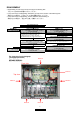
• Disassemble in order of the arrow of the figure of following flow.
下記フロー図の矢印の順番にはずしてください。
• In the case of the re-assembling, assemble it in order of the reverse of the following flow.
再組み立ての場合は、下記のフローの逆の順番に組立ててください
• In the case of the re-assembling, observe "attention of assembling" it.
再組み立ての場合は、「組立のご注意」を遵守してください。
TOP COVER SUB ASS
Y
REAR PANEL FRONT PANEL SUB ASSY ETHERNET UNIT
Refer to "EXPLOTED VIEW" Refer to "DISASSEMBLY 1.FRNOT PANEL SUB ASSY" Refer to "DISASSEMBLY 4.ETHERNET UNIT"
and "EXPLODED VIEW" and "EXPLODED VIEW"
MICON/FLD UNIT (Ref. No. of EXPLODED VIEW : 1-1 ) ETHERNET UNIT (Ref. No. of EXPLODED VIEW : 3 )
P.SW UNIT (Ref. No. of EXPLODED VIEW : 1-3 )
CONNECT UNIT (Ref. No. of EXPLODED VIEW : - )
ENCORDER UNIT (Ref. No. of EXPLODED VIEW : 1-2 )
INPUT UNIT & AUDIO SIGNAL UNI
T
Refer to "DISASSEMBLY 5.INPUT UNIT & AUDIO SIGNAL UNIT"
and "EXPLODED VIEW"
POWER SUPPLY UNIT INPUT UNIT (Ref. No. of EXPLODED VIEW : 4-1 )
Refer to "DISASSEMBLY 2.POWER SUPPLY UNIT" AUDIO SIGNAL UNIT (Ref. No. of EXPLODED VIEW : 4-2 )
and "EXPLODED VIEW"
POWER SUPPLY UNIT (Ref. No. of EXPLODED VIEW : 1-4 )
ETHERNET UNIT (6 units)
Refer to "DISASSEMBLY 6.ETHERNET UNIT (6 units)"
POWER TRANS SUB TRANS and "EXPLODED VIEW"
Refer to "EXPLOTED VIEW" Refer to "DISASSEMBLY 3.SUB TRANS" POWER AMP UNIT (Ref. No. of EXPLODED VIEW : 2 )
and "EXPLODED VIEW"
Front side
Picture BPicture E
Picture A
Picture C
Picture D
Picture F
Top view
The viewpoint of each photograph
(photography direction)
各図の視点(撮影方向)