AV SURROUND RECEIVER AVR-3801 OPERATING INSTRUCTIONS 2 We greatly appreciate your purchase of the AVR-3801. 2 To be sure you take maximum advantage of all the features the AVR-3801 has to offer, read these instructions carefully and use the set properly. Be sure to keep this manual for future reference, should any questions or problems arise. “SERIAL NO.
1 1
2 SAFETY PRECAUTIONS CAUTION WARNING: TO PREVENT FIRE OR SHOCK HAZARD, DO NOT EXPOSE THIS APPLIANCE TO RAIN OR MOISTURE. TO PREVENT ELECTRIC SHOCK, MATCH WIDE BLADE OF PLUG TO WIDE SLOT, FULLY INSERT. ATTENTION POUR ÉVITER LES CHOCS ÉLECTRIQUES, INTERODUIRE LA LAME LA PLUS LARGE DE LA FICHE DANS LA BORNE CORRESPONDANTE DE LA PRISE ET POUSSER JUSQU’ AU FOND. CAUTION RISK OF ELECTRIC SHOCK DO NOT OPEN CAUTION: TO REDUCE THE RISK OF ELECTRIC SHOCK, DO NOT REMOVE COVER (OR BACK).
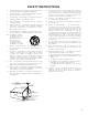
SAFETY INSTRUCTIONS 12. Power-Cord Protection – Power-supply cords should be routed so that they are not likely to be walked on or pinched by items placed upon or against them, paying particular attention to cords at plugs, convenience receptacles, and the point where they exit from the appliance. Heed Warnings – All warnings on the appliance and in the operating instructions should be adhered to. 14. Cleaning – The appliance should be cleaned only as recommended by the manufacturer. 4.
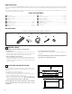
2 INTRODUCTION Thank you for choosing the DENON AVR-3801 Digital Surround A / V receiver. This remarkable component has been engineered to provide superb surround sound listening with home theater sources such as DVD, as well as providing outstanding high fidelity reproduction of your favorite music sources. As this product is provided with an immense array of features, we recommend that before you begin hookup and operation that you review the contents of this manual before proceeding.
3 CAUTIONS ON HANDLING • Switching the input function when input jacks are not connected A clicking noise may be produced if the input function is switched when nothing is connected to the input jacks. If this happens, either turn down the MASTER VOLUME control or connect components to the input jacks. • Whenever the power switch is in the STANDBY state, the apparatus is still connected on AC line voltage. Please be sure to unplug the cord when you leave home for, say, a vacation.
5 CONNECTIONS • Do not plug in the AC cord until all connections have been completed. • Be sure to connect the left and right channels properly (left with left, right with right). • Insert the plugs securely. Incomplete connections will result in the generation of noise. • Use the AC OUTLETS for audio equipment only. Do not use them for hair driers, etc. • Note that binding pin plug cords together with AC cords or placing them near a power transformer will result in generating hum or other noise.
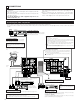
Connecting video components • To connect the video signal, connect using a 75 Ω/ohms video signal cable cord. Using an improper cable can result in a drop in video quality. • When making connections, also refer to the operating instructions of the other components. TV or DBS tuner Connecting a TV/DBS tuner TV/DBS • Connect the TV’s or DBS tuner’s video output jack (VIDEO OUTPUT) to the VIDEO (yellow) TV/DBS IN jack using a 75 Ω/ohms video coaxial pin plug cord.
Connecting a video component equipped with S-Video jacks • When making connections, also refer to the operating instructions of the other components. • A note on the S input jacks The input selectors for the S inputs and pin jack inputs work in conjunction with each other.
Connecting the antenna terminals DIRECTION OF BROADCASTING STATION AM LOOP ANTENNA (Supplied) FM ANTENNA 75 Ω/ohms COAXIAL CABLE 300 Ω/ohms FEEDER CABLE FM ANTENNA ADAPTER (Supplied) AM OUTDOOR ANTENNA FM INDOOR ANTENNA (Supplied) 300 Ω/ohms GROUND • An F-type FM antenna cable plug can be connected directly. • If the FM antenna cable’s plug is not of the F-type, connect using the included antenna adapter.
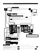
Connecting a Video Component Equipped with Color Difference (Component - Y, CR, CB) Video Jacks (DVD Player) • When making connections, also refer to the operating instructions of the other components. • The signals input to the color difference (component) video jacks are not output from the VIDEO output jack (yellow) or the S-Video output jack. In addition, the video signals input to the VIDEO input (yellow) and S-Video input jacks are not output to the color difference (component) video jacks.
Connecting the external input (EXT. IN) jacks Center Subwoofer Surround back Surround Front • These jacks are for inputting multi-channel audio signals from an outboard decoder, or a component with a different type of multi-channel decoder, such as a Super Audio DVD player, or a multi-channel SACD player, or other future multi-channel sound format decoder. • When making connections, also refer to the operating instructions of the other components.
Speaker system connections • Connect the speaker terminals with the speakers making sure that like polarities are matched (≈ with ≈ , √ with √ ). Mismatching of polarities will result in weak central sound, unclear orientation of the various instruments, and the sense of direction of the stereo being impaired. • When making connections, take care that none of the individual conductors of the speaker cord come in contact with adjacent terminals, with other speaker cord conductors, or with the rear panel.
Protector circuit • This unit is equipped with a high-speed protection circuit. The purpose of this circuit is to protect the speakers under circumstances such as when the output of the power amplifier is inadvertently short-circuited and a large current flows, when the temperature surrounding the unit becomes unusually high, or when the unit is used at high output over a long period which results in an extreme temperature rise.
6 PART NAMES AND FUNCTIONS Front Panel • For details on the functions of these parts, refer to the pages given in parentheses ( ). q Power ON/STANDBY switch....................................................(41) w Headphones jack (PHONES) ....................................................(44) e MULTI button ...........................................................................(46) r Surround speaker system indicators (SURROUND SPEAKER A/B) t AUTO button ............................................
Remote control unit • For details on the functions of these parts, refer to the pages given in parentheses ( ). Remote control signal transmitter ..............................................(29) POWER Power button..........................................(41) ON / SOURCE OFF RC-883 REMOTE CONTROL UNIT DISPLAY/SURR. PARA button .....................................................(52) System setup/ system buttons ......................................
7 SETTING UP THE SYSTEM • Once all connections with other AV components have been completed as described in “CONNECTIONS” (see pages 6 to 13), make the various settings described below on the monitor screen using the AVR-3801’s on-screen display function. These settings are required to set up the listening room’s AV system centered around the AVR-3801. • Use the following buttons to set up the system: SYSTEM SETUP button Press this to display the system setup menu. DISPLAY MENU SURR. PARA.
• Speaker system layout Basic system layout • The following is an example of the basic layout for a system consisting of eight speaker systems and a television monitor: Subwoofer Center speaker system Surround back speaker systems Front speaker systems Set these at the sides of the TV or screen with their front surfaces as flush with the front of the screen as possible.
Before setting up the system 1 2 Check that all the connections are correct, then turn on the main unit’s power. Display the System Setup Menu. SETUP Setting the power amplifier assignment Make this setting to switch the power amplifier for the surround back channel to Multi. 1 TUNING BAND ENTER MODE At the System Setup Menu, select “Power Amp Assignment” and press the ENTER button SHIFT TUNING 2 Select “Surround Back” to use as the surround back channel, “Multi” to use as multi zone out.
2 Switch to the speaker configuration screen. ENTER SHIFT 3 TUNING BAND MODE Set whether or not speakers are connected and, if so, their size parameters. • To select the speaker TUNING Center Sp. • To select the parameter TUNING Front Sp. BAND MODE Subwoofer TUNING Surround Sp. A Surround back Sp. Surround Sp. B 4 Enter the setting. a) If no surround speakers are used (if “None” is set for both A and B): The Subwoofer Mode screen appears.
2 Enter the setting. When “Front” is set to “Large” and “Subwoofer” is set to “Yes”, the set switches to the subwoofer mode. ENTER SHIFT Speaker type setting when using both surround speakers A and B If “Small” is set for either surround speakers A or B, the output is the same as when “Small” is set for both A and B. Setting the Subwoofer mode 1 Select the Subwoofer mode. TUNING BAND MODE TUNING 2 Enter the setting. The System Setup Menu reappears.
2 Select the desired setting. TUNING BAND MODE TUNING 3 We recommend setting this to “OFF”. When set to “ON”, the operation for software for which no identification signals are recorded is set. Enter the setting. The System Setup Menu reappears. ENTER SHIFT Setting OFF............Set the “OFF” mode to perform 6.1-channel playback with conventional 5.1-channel sources or sources on which the identification signal described below is not recorded. ON .............
2 Switch to the Delay Time screen. ENTER SHIFT 3 Select the desired unit, meters or feet. Select (darken) the desired units, “Meters” or “Feet”. TUNING BAND MODE TUNING Example: When “Feet” is selected 4 Once “Meters” or “Feet” is selected in step 3, the Delay Time screen appears automatically. 5 Select the speaker to be set. TUNING BAND MODE TUNING 6 TUNING BAND MODE TUNING Set the distance between the center speaker and listening position. The distance changes in units of 1 foot (0.
7 Enter the setting. The System Setup Menu reappears. The AVR-3801 automatically sets the optimum surround delay time for the listening room. ENTER SHIFT NOTE: • If the distance unit is changed after the delay time is set, the settings are reset to the factory default values (see page 16). Setting the channel level • • • • Use this setting to adjust so that the playback level between the different channels is equal.
Select “Test Tone Start”. 6 TUNING BAND MODE TUNING 7 Select “Yes”. TUNING BAND MODE TUNING 8 a. If the “Auto” mode is selected: Test tones are automatically emitted from the different speakers.
When you adjust the channel levels while in the SYSTEM SETUP CHANNEL LEVEL mode, the channel level adjustments made will affect ALL surround modes. Consider this mode a Master Channel Level adjustment mode. After you have completed the SYSTEM SETUP CHANNEL LEVEL adjustments, you can then activate the individual surround modes and adjust channel levels that will be remembered for each of those modes.
Multi Vol. Level Set the multi pre-out output level adjustment. 1 ENTER TUNING At the “System Setup Menu” screen, select “Multi Vol. Level” and press the ENTER button. SHIFT BAND MODE TUNING 2 Select the desired settimg. TUNING BAND MODE TUNING 0 dB, -40 dB: The output level is fixed at the set level and the volume can no longer be adjusted. Variable: The level can be adjusted freely using the buttons on the remote control unit. 3 Enter the setting. The “System Setup Menu” reappears.
4 Enter the setting. The System Setup Menu reappears. ENTER SHIFT Auto tuner presets Use this to automatically search for FM broadcasts and store up to 40 stations at preset channels A1 to 8, B1 to 8, C1 to 8, D1 to 8 and E1 to 8. NOTE: • If an FM station cannot be preset automatically due to poor reception, use the “Manual tuning” operation to tune in the station, then preset it using the manual “Preset memory” operation.
After completing system setup This button can be pressed at any time during the system setup process to complete the process. 1 At the System Setup Menu, press the SYSTEM SETUP button. The changed settings are entered and the on-screen display turns off.
8 REMOTE CONTROL UNIT • The included remote control unit (RC-883) can be used to operate not only the AVR-3801 but other remote control compatible DENON components as well. In addition, the memory contains the control signals for other remote control units, so it can be used to operate non-Denon remote control compatible products. Inserting the batteries q Remove the remote control unit’s rear cover. w Set three R6P/AA batteries in the battery compartment in the indicated direction.
Operating DENON audio components 1 Use the mode selector buttons to select the component you want to operate. The mode switches between “AMP”, “TUNER” and “MULTI” each time the RECEIVER button is pressed, between “CDR”, “MD” and “TAPE” each time the CDR/MD/TAPE button is pressed, between “DBS” and “CABLE” each time the DBS/CABLE button is pressed, and between “DVD” and “DVD SETUP” each time the DVD button is pressed, and between “VCR” and “VCR2” eachtime the VCR button is pressed.
Preset memory By using the preset memory, the included remote control unit can be used to control other makes of video equipment. Note that this is not possible for some models, however. In such cases, use the learning function (see page 34) to store the remote control signals in the remote control unit’s memory. See page 37 for instructions on resetting the data stored in the preset memory. 1 Press the power ON/SOURCE button and the OFF button at the same time.
Checking the preset memory settings 1 Press the power ON/SOURCE button and the OFF button at the same time. • “SET UP” appears on the remote control unit’s display. 4 Press the D and H cursor buttons to display the registered preset memory on the remote control unit’s display and check. TUNING ON / SOURCE OFF BAND MODE TUNING 2 Press the ENTER button. 5 ENTER Press the ENTER button to terminate.
2 Operate the component. • For details, refer to the component’s operating instructions. Some models cannot be operated with this remote control unit. 1.
Learning function If your AV component is not a Denon product or if it cannot be operated using the preset memory, it can be controlled with the included remote control unit by storing its remote control signals in the remote control unit. 1 Press the power ON/SOURCE button and the OFF button simultaneously. • “SET UP” appears on the remote control unit’s display.
System call The included remote control unit is equipped with a system call function allowing a series of remote control signals to be transmitted by pressing a single button. This function can be used for example to turn on the amplifier’s power, select the input source, turn on the monitor TV’s power, turn on the source component’s power and set the source to the play mode, all at the touch of a button.
5 Use the D and H cursor buttons to select the mode for the button at which the system call signals are to be registered, then press the ENTER button. 7 q Press the mode selector button according to the button with the remote control signals to be registered. TV CD VCR DBS/CABLE CDR/MD/ TAPE RECEIVER TUNING ENTER BAND MODE VDP DVD SHIFT TUNING w Press the buttons with the remote control signals to be registered one at a time. 6 “SELECT KEY” is displayed.
4 q To reset CALL 1 or CALL 2, select “SYS CALL 1” or SYS CALL 2”, then press the ENTER button. Use the D and H cursor buttons to display “RESET SYS” on the remote control unit, then press the ENTER button. • “SYS SEL” appears on the remote control unit’s display.
4 Use the D and H cursor buttons to display “RESET PRE” on the remote control unit, then press the ENTER button. • After “SEL PRE” is displayed on the remote control unit’s display, the registered preset memory is displayed on the remote control unit’s display. 6 When the mode you want to reset is shown on the remote control unit’s display, press the ENTER button to reset the preset memory. ENTER SHIFT TUNING ENTER BAND MODE SHIFT 7 TUNING 5 “CONFIRM” is displayed.
(4) All reset function • This function is for resetting all the settings to the factory defaults. 1 Press the power ON/SOURCE button and the OFF button at the same time. “SET UP” appears on the remote control unit’s display. POWER 1 ON / SOURCE OFF ON / SOURCE OFF RC-883 REMOTE CONTROL UNIT TV CD VCR DBS/CABLE CDR/MD/ TAPE RECEIVER VDP DVD MENU DISPLAY SURR. PARA. OSD SETUP RETURN TUNING 2 3, 4 Press the ENTER button.
Auto search function • The set is equipped with a function for searching for the registration number if you do not know the preset code (a 4-digit number) when setting the preset memory. 1 2 For TV, DBS or CABLE components, turn on the component’s power. For CD, MD, TAPE, DVD, VCR and VDP component’s, turn on the component’s power and load a disc or tape. Press the power ON/SOURCE button and the OFF button at the same time. • “SET UP” appears on the remote control unit’s display.
9 OPERATION Before operating 1 2 Refer to “CONNECTIONS” (pages 6 to 13) and check that all connections are correct. Select “AMP” using the RECEIVER button. (only when operating with the remote control unit) RECEIVER (Remote control unit) 3 Turn on the power. Press the POWER switch (button). POWER ON / SOURCE OFF RC-883 REMOTE CONTROL UNIT ON / STANDBY ON / SOURCE 3 ON/STANDBY Light (Main unit) (Remote control unit) When pressed, the power turns on and the display lights.
Playing the input source TV CD VCR DBS/CABLE CDR/MD/ TAPE RECEIVER 1 VDP DVD MENU DISPLAY SURR. PARA. OSD SETUP RETURN TUNING A/B MEMORY BAND MODE CHANNEL VOLUME TUNING + 1 Select the input source to be played. Example: CD SKIP ENTER - SHIFT SKIP MUTING TUNER PHONO CD 1 2 3 VDP DVD 4 5 6 VCR-1 VCR-2 /V.AUX TV/DBS 7 8 9 0 TEST TONE CD 4 - CDR/ TAPE TV/ VCR FUNCTION + SPEAKER +10 OUTPUT SURROUND 3 DOLBY/DTS SURROUND DSP SIMU. 5CH / 7CH STEREO 6.1 / 7.
• Selecting the PCM mode Press the PCM button to switch to the PCM signal input. Input mode display One of these lights, depending on the input signal. • In the AUTO mode PCM INPUT AUTO PCM DTS DIGITAL ANALOG • In the DIGITAL PCM mode INPUT (Main unit) AUTO • Selecting the DTS mode Press the DTS button to switch to the DTS signal input.
After starting playback [1] Adjusting the sound quality (TONE) The tone control function will not work in the direct mode. 1 The tone switches as follows each time the TONE CONTROL button is pressed. TONE CONTROL BASS TREBLE (Main unit) 2 With the name of the volume to be adjusted selected, turn the SELECT knob to adjust the level. SELECT (Main unit) • To increase the bass or treble: Turn the control clockwise. (The bass or treble sound can be increased to up to +12 dB in steps of 2 dB.
[4] Combining the currently playing sound with the desired image 1 Simulcast playback Use this switch to monitor a video source other than the audio source. Press the VIDEO SELECT button repeatedly until the desired source appears on the display. Cancelling simulcast playback. VIDEO SELECT (Main unit) • Select “SOURCE” using the VIDEO SELECT button. • Switch the program source to the component connected to the video input. [5] Checking the currently playing program source, etc.
[2] Outputting a program source to an amplifier, etc., in a different room (MULTI mode) 1 Press the MULTI button. The display switches as follows each time the button is pressed. MULTI (Main unit) 2 With “M-SOURCE SOURCE” displayed, turn the FUNCTION knob and select the source you wish to output. • The “MULTI” indicator and the indicator of the selected source light. FUNCTION (Main unit) 3 Start playing the source to be output.
Playback using the external input (EXT. IN) jacks 1 Set the external input (EXT. IN) mode. Press the EXT. IN to switch the external input. EXT.IN EXT.IN (Main unit) (Remote control unit) Once this is selected, the input signals connected to the FL (front left), FR (front right), C (center), SL (surround left), SR (surround right), SBL (surround back left) and SBR (surround back right) channels of the EXT.
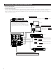
Multi-source and multi-zone playback MULTI ROOM MUSIC ENTERTAINMENT SYSTEM • When the outputs of the MULTI ZONE PRE OUT terminals are wired and connected to integrated amplifiers installed in other rooms, different sources can be played in rooms other than the main room in which this unit and the playback devices are installed. (Refer to ANOTHER ROOM on the diagram below.) • MULTI ZONE SPEAKER OUT can be used when “Multi” is selected at System Setup Menu “Power Amp Assignment”.
10 SURROUND Before playing with the surround function • Before playing with the surround function, be sure to use the test tones to adjust the playback level from the different speakers. This adjustment can be performed with the system setup (see page 23) or from the remote control unit, as described below. • Adjusting with the remote control unit using the test tones is only possible in the “Auto” mode and only effective in the DOLBY/DTS SURROUND modes.
Fader function • This function makes it possible to lower the volume of the front channels (FL, C and FR) or the rear channels (SL, SR, SBL and SBR) together. Use it for example to adjust the balance of the sound from the different positions when playing multi-channel music sources. 1 Select “FADER”. CH.VOL ENTER SHIFT (Main unit) (Remote control unit) The channel switches in the order shown below each time this button is pressed.
Dolby Digital mode (only with digital input) and DTS Surround mode (only with digital input) 1 Select the input source. Playback with a digital input q Select an input source set to digital (COAXIAL/OPTICAL) (see page 25). FUNCTION VDP 5 (Main unit) (Remote control unit) w Set the input mode to “AUTO” or “DTS”. AUTO DTS MODE (Main unit) (Remote control unit) POWER ON / SOURCE OFF 2 Select the Dolby/DTS Surround mode.
4 SURROUND PARAMETER (Main unit) Display the surround parameter menu. SURR. PARA. (Remote control unit) (When displayed with the remote control unit) 5 6 Select the various parameters. SURROUND PARAMETER TUNING BAND Adjust the parameter settings. SELECT TUNING MODE BAND TUNING (Main unit) (Remote control unit) (When displayed with the buttons on the main unit) MODE TUNING (Main unit) (Remote control unit) 6.1 / 7.1 Surround: “ON” ........
11 DSP SURROUND SIMULATION • The AVR-3801 is equipped with a high performance DSP (Digital Signal Processor) which uses digital signal processing to synthetically recreate the sound field. One of seven preset surround modes can be selected according to the program source and the parameters can be adjusted according to the conditions in the listening room to achieve a more realistic, powerful sound.
DSP surround simulation • To operate the surround mode and surround parameters from the remote control unit. 1 Select the surround mode for the input channel. VCR 2, 4 SURROUND DOLBY/DTS SURROUND 5CH / 7CH STEREO DSP SIMU. DBS/CABLE VDP DVD MENU DISPLAY SURR. PARA. OSD SETUP RETURN TUNING 6.1 / 7.
• Operating the surround mode and surround parameters from the main unit‘s panel. 1 Turn the SELECT knob to select the surround mode.
Tone control setting • Use the tone control setting to adjust the bass and treble as desired. • To operate the tone control from the remote control unit. 1 Display the surround parameter screen on the monitor. The screen for the selected surround mode appears. “TONE” cannot be selected in the Direct mode. SURR. PARA. POWER ON / SOURCE OFF RC-883 REMOTE CONTROL UNIT (Remote control unit) Select “TONE”. 2 1, 6 TUNING TV CD VCR DBS/CABLE CDR/MD/ TAPE RECEIVER VDP DVD MENU DISPLAY SURR.
Surround parameters w MODE: (DTS NEO:6) • Cinema This mode is optimum for playing movies. Decoding is performed with emphasis on separation performance to achieve the same atmosphere with 2-channel sources as with 6.1-channel sources. This mode is effective for playing sources recorded in conventional surround formats as well, because the in-phase component is assigned mainly to the center channel (C) and the reversed phase component to the surround (SL, SR and SB channels).
12 LISTENING TO THE RADIO Auto tuning 1 Set the input function to “TUNER”. FUNCTION TUNER 1 (Main unit) 2 (Remote control unit) Press the RECEIVER button on the remote control unit to select “TUNER”. RECEIVER POWER ON / SOURCE OFF (Remote control unit) RC-883 REMOTE CONTROL UNIT 3 Watching the display, press the BAND button to select the desired band (AM or FM). TUNING BAND TV CD VCR DBS/CABLE CDR/MD/ TAPE RECEIVER 2 MODE VDP DVD TUNING MENU DISPLAY SURR. PARA.
5 TUNING BAND MODE TUNING NOTES: • When in the auto tuning mode on the FM band, the “STEREO” indicator lights on the display when a stereo broadcast is tuned in. At open frequencies, the noise is muted and the “TUNED” and “STEREO” indicators turn off. • When the manual tuning mode is set, FM stereo broadcasts are received in monaural and the “STEREO” indicator turns off. Press the TUNING UP or DOWN button to tune in the desired station. The frequency changes continuously when the button is held in.
Recalling preset stations • To call out preset stations from the remote control unit. 1 ENTER SHIFT Watching the display, press the SHIFT button to select the preset memory block. TV CD VCR DBS/CABLE CDR/MD/ TAPE RECEIVER VDP DVD MENU DISPLAY SURR. PARA. OSD SETUP RETURN TUNING A/B (Remote control unit) MEMORY BAND MODE CHANNEL 2 CHANNEL + SKIP - Watching the display, press the CHANNEL + (UP) or – (DOWN) button to select the desired preset channel.
15 TROUBLESHOOTING If a problem should arise,first check the following. 1. Are the connections correct ? 2. Have you operated the receiver according to the Operating Instructions ? 3. Are the speakers, turntable and other components operating property ? If this unit is not operating properly, check the items listed in the table below. Should the problem persist, there may be a malfunction. Disconnect the power immediately and contact your store of purchase.
16 ADDITIONAL INFORMATION Optimum surround sound for different sources There are currently various types of multi-channel signals (signals or formats with more than two channels). 2 Types of multi-channel signals Dolby Digital, Dolby Pro Logic, DTS, high definition 3-1 signals (Japan MUSE Hi-Vision audio), DVD-Audio, SACD (Super Audio CD), MPEG multichannel audio, etc. “Source” here does not refer to the type of signal (format) but the recorded content. Sources can be divided into two major categories.
Surround back speakers A 6.1-channel system is a conventional 5.1-channel system to which the “surround back” (SB) channel has been added. This makes it easy to achieve sound positioned directly behind the listener, something that was previously difficult with sources designed for conventional multi surround speakers.
Speaker setting examples Here we describe a number of speaker settings for different purposes. Use these examples as guides to set up your system according to the type of speakers used and the main usage purpose. 1. DTS-ES compatible system (using surround back speakers) (1) Basic setting for primarily watching movies This is recommended when mainly playing movies and using regular single way or 2-way speakers for the surround speakers.
(3) When using different surround speakers for movies and music To achieve more effective surround sound for both movies and music, use different sets of surround speakers and different surround modes for the two types of sources. Front speakers Center speaker Monitor Subwoofer 45° ~ 60° Surround speakers A • Set the front speakers slightly wider apart than the setup for watching movies only and point them toward the listening position in order assure clear positioning of the sound.
Surround The AVR-3801 is equipped with a digital signal processing circuit that lets you play program sources in the surround mode to achieve the same sense of presence as in a movie theater. Dolby Surround (1) Dolby Digital (Dolby Surround AC-3) Dolby Digital is the multi-channel digital signal format developed by Dolby Laboratories. Dolby Digital consists of up to “5.
(2) Dolby Pro Logic Dolby Pro Logic is a multi-channel signal playback system developed by Dolby Laboratories which decodes sources recorded in Dolby Surround into four channels: front left, center, front right and surround (the surround channel is monaural, but is played through two surround speakers). Here, “sources recorded in Dolby Surround” are sources on which surround signals (three channels or more) are recorded onto two channels using Dolby Surround encoding technology.
DTS-ES Extended Surround TM DTS-ES Extended Surround is a new multi-channel digital signal format developed by Digital Theater Systems Inc. While offering high compatibility with the conventional DTS Digital Surround format, DTS-ES Extended Surround greatly improves the 360-degree surround impression and space expression thanks to further expanded surround signals. This format has been used professionally in movie theaters since 1999. In addition to the 5.
System setup items and default values (set upon shipment from the factory) System setup q w Default settings Power AMP Assignment Set this to switch the surround back channel’s power amplifier for use for multi-zone. Speaker Configuration Input the combination of speakers in your system and their corresponding sizes (SMALL for regular speakers, LARGE for fullsize, full-range) to automatically set the composition of the signals output from the speakers and the frequency response.
17 SPECIFICATIONS 2 Audio section • Power amplifier Rated output: Front: Dynamic power: Output terminals: • Analog Input sensitivity / input impedance: Frequency response: S/N: Distortion: Rated output: • Digital D/A output: 2 2 2 2 105 W + 105 W (8 150 W + 150 W (6 Center: 105 W (8 150 W (6 Surround: 105 W + 105 W (8 150 W + 150 W (6 Surround Back: 105 W + 105 W (8 150 W + 150 W (6 140 W x 2 ch (8 Ω/ohms) 210 W x 2 ch (4 Ω/ohms) 240 W x 2 ch (2 Ω/ohms) Front, Center, Surr.
14-14, AKASAKA 4-CHOME, MINATO-KU, TOKYO 107-8011, JAPAN Telephone: (03) 3584-8111 Printed in Japan 511 3663 106