Bar Code Handy Terminal BHT-202B-CE/202BW-CE User’s Manual
If you leave the BHT with the battery cartridge discharged or with no battery cartridge loaded or if you replace the battery cartridge in a wrong way, the BHT may lose the data stored in it. Before cold booting (refer to Chapter 2, Section 2.3.5 "Warm and Cold Booting"), it is recommended that important data be saved into the FLASH folder or uploaded to the host computer. Cold booting will erase all data stored in the RAM.
US and Canada Regulations This device complies with Part 15 of the FCC Rules, Canadian ICES-003 and RSS-210 Rules. Operation is subject to the following two conditions: (1) this device may not cause harmful interference, and (2) this device must accept any interference received, including interference that may cause undesired operation. NOTE: This equipment has been tested and found to comply with the limits for a Class A digital device, pursuant to Part 15 of the FCC Rules.
LABELING: For USA and Canada For USA and Canada Grip style BHT For USA and Canada
Declaration of Conformity (For European Union) The radio frequency module (Type: LA-4137) that complies with the Directive 99/5/EC(R&TTE) is mounted on this device (BHT-202BW-CE). A Declaration of Conformity may be obtained from: http://www2.symbol.
Preface Please READ through these operating instructions carefully. It will enable you to operate your BHT-202B-CE/202BW-CE correctly. The following contents are explained in this guide: • Handling and operating methods for the BHT-202B-CE/202BW-CE • Communication • Error messages • Specifications • Handling and operating methods for the optical communication unit CU-200 series The BHT-202B-CE/202BW-CE models are designed in the same way except for the interface differences shown in the table below.
How this book is organized This manual is made up of five chapters and appendices. Chapter 1 Quick Guide Describes the basic operating method of the BHT and the related notes. Chapter 2 Getting Started the BHT and System Menu Summarizes the BHT system configuration and describes the operation including preparation and System Mode (which is required for the efficient use of application programs).
Related Publications BHT-200-CE API Reference Manual BHT-200-CE Class Library Reference Manual 2D Code Scanner/Barcode Scanner Keyboard Interface with BHT-CE kbifCE User’s Guide Screen Indication The lettering in the screens in this manual is a little different from that in the actual screens. File names used are only for description purpose, so they will not appear if you have not set files having those names.
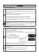
SAFETY PRECAUTIONS Be sure to observe all these safety precautions. Please READ through this manual carefully. It will enable you to use the BHT and CU correctly. Always keep this manual nearby for speedy reference. Strict observance of these warnings and cautions is a MUST for preventing accidents that could result in bodily injury and substantial property damage. Make sure you fully understand all definitions of these terms and symbols given below before you proceed to the text itself.
Handling the battery cartridge • Never disassemble or heat the battery cartridge, nor put it into fire or water; doing so could cause battery-rupture or leakage of battery fluid, resulting in a fire or bodily injury. • Do not carry or store the battery cartridge together with metallic ball-point pens, necklaces, coins, hairpins, etc. Doing so could short-circuit the terminal pins, causing the batteries to rupture or the battery fluid to leak, resulting in a fire or bodily injury.
Handling the CU • If smoke, abnormal odors or noises come from the CU, immediately unplug the AC adapter from the wall socket or CU and contact your nearest dealer. Failure to do so could cause fire or electrical shock. • If foreign material or water gets into the CU, immediately unplug the AC adapter from the wall socket or CU and contact your nearest dealer. Failure to do so could cause fire or electrical shock.
Handling the battery cartridge • Never charge a wet or damp rechargeable battery cartridge. Doing so could cause the batteries to break, generate heat, rupture or burn. Handling the BHT • If smoke, abnormal odors or noises come from the BHT, immediately turn off the power, pull out the battery cartridge, and contact your nearest dealer. Failure to do so could cause smoke or fire.
Handling the CU • Never disassemble or modify the CU; doing so could result in an accident such as fire or malfunction. • Never put the CU in places where there are excessively high temperatures, such as inside closed-up automobiles, or in places exposed to direct sunlight. Doing so could affect the housing or parts, resulting in a fire. • Avoid using the CU in extremely humid or dusty areas, or where there are drastic temperature changes.
Proper Care of the BHT and CU Clean the housings, BHT charge terminals, battery cartridge terminals, and CU-200 charge terminals with a dry, soft cloth. Before cleaning, be sure to turn the BHT power off and unplug the AC adapter of the CU. • Never use benzene, alcohol, or other organic solvents. The housing may be marred or the paint may come off. • Never rub or strike the liquid crystal display (LCD) with anything hard. The LCD surface will be easily scratched or broken.
DENSO WAVE INCORPORATED does not assume any product liability arising out of, or in connection with, the application or use of any product, circuit, or application described herein. If it is judged by DENSO WAVE INCORPORATED that malfunction of the product is due to the product having been dropped or subjected to impact, repairs will be made at a reasonable charge even within the warranty period.
Chapter 1 Quick Guide Chapter 2 Getting Started the BHT and System Menu Chapter 3 Communications Operations of the BHT-202B-CE/202BW-CE Chapter 4 Error Messages Chapter 5 Handling the CU-200 (Option) Appendices
Chapter 1 Quick Guide This chapter describes the basic operating method of the BHT and the related notes. 1.1 Reading Bar Codes ..........................................................................................................................................2 1.2 Setting and Using the Hand Strap and Stylus ..................................................................................................4 1.3 Setting the Backlight.................................................................
1.1 Reading Bar Codes Turn the BHT on, bring the bar-code reading window to the bar code to be scanned, and press the trigger switch. Pressing the trigger switch halfway emits a laser light to indicate the scanning range and pressing it fully turns on the illumination LED to scan the bar code. When the BHT has read the bar code successfully, the indicator LED will illuminate in blue. Bar code scanning range indicated by the laser light Max. 70 cm (27.
Chapter 1 Quick Guide • If the BHT fails to read due to specular effects or other factors, change the scanning angle of the reading window or the distance from codes as shown at right, and try it again. (Specular effects occur when the reflection of the light from the bar code becomes excessively strong. This can easily happen when the reflecting surface is polished or covered with vinyl.) • The laser light indicates the scanning range as a guide.
1.2 Setting and Using the Hand Strap and Stylus Setting the hand strap Hand strap Using the hand strap Put your hand through the hand strap and hold the BHT as shown below. This will prevent you from dropping the BHT accidentally.
Chapter 1 Quick Guide Using the stylus The BHT has a touch screen LCD. With the stylus that comes with the BHT, you can operate keys, menus, and icons displayed on the touch screen. Before using the touch screen, be sure to set it up. (Refer to Chapter 2, Section 2.3.2, "Setting-up 2: Calibrating the touch screen.") • Always use the stylus to operate the touch screen. Do not use your fingernails or any pointed or hard object or apply a strong pressure or impact to the LCD.
1.3 Setting the Backlight Pressing the right-hand trigger switch (M4 key) with the SF/ALP key held down activates or deactivates the backlight function. Backlight Off or Dim (The backlight function is Disable when you turn the BHT power on.) Press the right-hand trigger switch while holding down SF/ALP. Right-hand trigger switch (M4) Backlight On Press the right-hand trigger switch while holding down SF/ALP. If no key is pressed for 3 seconds.
Chapter 1 Quick Guide 1.4 Using the Keypad Entering Numerical Data To enter numerical data, use the numerical keys and the ENT key. For example, to enter the number "120," press the 1, 2 and 0 keys and then press the ENT key. If you type in any wrong value, press the C/BS (BS) key and then enter the correct one. Entering alphabetic characters The alphabet entry procedure differs depending upon the keypad type. 30-key pad Holding down the SF/ALP key only for the specified period (1.
1.5 Transferring Data Using radio link (BHT-202BW-CE only) Using radio waves, the BHT-202BW-CE may transfer data to an access point in a spread spectrum communications system. If there are too many communications errors, first make sure that the BHT-202BW-CE points directly at an access point. Host computer Access point Built-in antenna For data transfer using radio link, it is necessary to configure a wireless local area network (wireless LAN) connecting the BHT-202BW-CE and access points.
Chapter 1 Quick Guide Using infrared link Using infrared rays, the BHT may transfer data directly to the host computer equipped with an IrDA interface port and other IrDA-compliant devices. • Make sure that there is no obstruction in the light path between the BHT and any target stations. In infrared communication, you need to keep the BHT and any target stations within the effective infrared radiation range, usually 15 cm (5.9").
Using USB interface Using a USB interface cable, the USB interface ports of the BHT and a host computer can be connected, allowing data to be transferred to the host computer. Host computer BHT USB interface cable Using connector interface Using a connector interface cable, the RS-232C interface of a host computer and the connector interface port of the BHT can be connected allowing data to be transferred to the host computer.
Chapter 2 Getting Started the BHT and System Menu This chapter summarizes the BHT system configuration and describes the operation including preparation and System Menu (which is required for the efficient use of application programs). 2.1 BHT System Configuration .............................................................................................................................12 2.2 Components ....................................................................................................
2.1 BHT System Configuration The BHT barcode data collection system requires the following hardware as well as the BHT Bar Code Handy Terminal (which reads bar codes and accepts keypad entry), depending upon the intended system configuration. • Host computer: Allows you to edit, manage and download user programs and data, as well as downloading system programs.
Chapter 2 Getting Started the BHT and System Menu In addition, the BHT-202BW-CE may operate in a radio communications system (spread spectrum communication) by connecting with access points by a wireless local area network (wireless LAN).
BHT Operating System (OS) Microsoft Windows CE .NET 5.
Chapter 2 Getting Started the BHT and System Menu Application Development Tool Microsoft eMbedded Visual C++ 4.0 Service Pack 4 or later, Microsoft Visual Studio .NET or Microsoft Visual Studio .NET 2003 You can download Microsoft eMbedded Visual Tools 4.0 and Service Pack 4 from the Microsoft Web site at: (Microsoft eMbedded Visual C++ 4.0) http://www.microsoft.com/downloads/details.aspx?displaylang=en&FamilyID=1dacdb3d-50d1-41b2a107-fa75ae960856 (Service Pack 4) http://www.microsoft.
2.2 Components 2.2.1 Names and Functions * Provided on the BHT-202BW-CE Synchronization LED* Flashes during wireless communication. Indicator LED Illuminates in blue when the BHT has successfully read a bar code. Charge LED Illuminates in red during charging and turns green at completion of charging. Built-in antenna* Do not cover this antenna section with metalevaporated tape or by hand. Doing so may result in communications failures.
Chapter 2 Getting Started the BHT and System Menu Grip style BHT Trigger switch (M5 key) Press this switch to start bar code reading. • Press this halfway to emit a laser light. • Press this fully to scan a bar code.
The functions of the keys may be set by user programs. Shown below is a set of sample functions. 30-key pad Power key Turns the BHT on or off. Trigger switch (M3 key) Trigger switch (M4 key) C (Clear)/ BS (Backspace) key Moves back one character. Pressing this key with the SF key held down in BhtShell returns to the previous screen. SF (Shift)/ALP (Alphabet) key Used in combination with numerical keys for special input procedures. Holding down this key for 1.
Chapter 2 Getting Started the BHT and System Menu 26-key pad Power key Turns the BHT on or off. Trigger switch (M3 key) Trigger switch (M4 key) Magic keys [M1] to [M5]* These keys may be used as an SF key, ENT key, CTRL key, ALT key, TAB key, CLEAR key, backlight function on/off key, laser lighting key, or trigger switch depending upon definition in System Menu or in user programs. Although [M3] to [M5]* are set as trigger switches by default, user-defined virtual key codes can be assigned to them.
2.2.2 Status Indicators on the LCD Windows desktop on 30-key pad type Windows desktop on 26-key pad type Status indicators Status indicators Battery voltage level Shows the current battery voltage level. Displays when the voltage level is high. Displays when the voltage level is low. The grip style BHT shows two icons as shown below. The upper one is for the battery cartridge loaded in the BHT body and the lower one for that in the grip.
Chapter 2 Getting Started the BHT and System Menu Synchronization state (Provided on the BHT-202BW-CE) Displays the open state of the wireless device and the radio field intensity. Displays when the wireless device is open. Shows the radio field intensity with the number of bars. The radio field intensity icons ( , , and ) indicate that the radio link is established but do not assure you that there will be few communications errors.
2.2.3 Notes for Using the BHT Windows desktop on the LCD The Windows desktop shown in this manual may be a little different from that in the actual screens on the LCD. (Windows desktop sample) This task tray also may be a little different from that in the actual screen. No refreshing of the LCD screen when on standby To minimize the power consumption, the BHT automatically switches to the standby mode after it has not been operated for the specified period*.
Chapter 2 Getting Started the BHT and System Menu 2.3 Preparation 2.3.1 Setting-up 1: Loading the battery cartridge Before the first use of the BHT, be sure to load the battery cartridge as shown below. The battery cartridge is not loaded in the BHT when shipped from the factory. Into the BHT body (1) Turn the BHT upside down. (2) Slide the release buttons in the direction shown below and remove the battery cartridge cover. (3) Push the battery cartridge into the BHT.
Into the grip (1) Take the bottom cover off the grip by removing the screw. Grip Bottom cover Screw (2) Pull the lock in the direction of the arrow and insert the battery cartridge into the grip with the boss facing as shown below. Boss Battery cartridge Lock (3) Secure the bottom cover to the grip with the screw.
Chapter 2 Getting Started the BHT and System Menu • Never disassemble or heat the battery cartridge, nor put it into fire or water; doing so could cause battery-rupture or leakage of battery fluid, resulting in a fire or bodily injury. • Do not carry or store the battery cartridge together with metallic ball-point pens, necklaces, coins, hairpins, etc. Doing so could short-circuit the terminal pins, causing the batteries to rupture or the battery fluid to leak, resulting in a fire or bodily injury.
Battery Voltage Level on the Status Indicator Line The battery voltage level is always displayed on the status indicator line. (For details, refer to Section 2.2.2 "Status Indicators on the LCD.") Low Battery Indication Low battery warning If the battery output voltage drops below a specified lower level limit when the BHT is in operation, the BHT displays the following message for approx. 2 seconds and beeps three times. After that, it will resume previous regular operation.
Chapter 2 Getting Started the BHT and System Menu Grip style BHT As long as the voltage level of either one of battery cartridges loaded in the BHT body and grip is higher than the specified level, no low battery messages will appear. If any low battery message appears, therefore, you need to replace both battery cartridges. Even if you only have one fully-charged replacement battery cartridge on hand, remove both batteries.
2.3.2 Setting-up 2: Calibrating the touch screen Press the power key to turn on the BHT. The calibration screen appears, so follow the on-screen instructions. If nothing appears, first perform a "cold boot" (refer to Section 2.3.5). The "+" appears first at the center of the screen as shown at left. Tap the center of the "+" with the stylus for one second, and the "+" moves to the upper left. Tap its center, and it moves to the bottom left.
Chapter 2 Getting Started the BHT and System Menu 2.3.3 Battery Replacement Notes When is battery replacement needed? If the "Charge the battery!" appears on the LCD, replace the battery cartridge with a fully charged one. If you leave the BHT without replacing the battery cartridge, then the integrated calendar clock or data will no longer be backed up so that the calendar clock may stop or the data may be lost.
2.3.4 BHT Turning-off Notes [ 1 ] "Shutdown in progress" message If you press the power key to turn off the BHT, the BHT displays the following message and starts preparation for shutdown. When the above message is displayed, do not remove the battery cartridge. If you do so, the data stored in the BHT may be lost.
Chapter 2 Getting Started the BHT and System Menu [ 2 ] Backing up the Registry The Registry is the part of Windows CE that stores setup information required for operating the BHT. Backing-up the Registry When the BHT is on, pressing the power key with the SF/ALP (SF) key held down displays the screen shown at right and starts backing up the Registry. Do not remove the battery cartridge until the backup operation is completed and the message disappears.
2.3.5 Warm and Cold Booting Warm-booting the BHT In any of the following cases, warm-boot the BHT: - The BHT makes no response to entry from the touch screen or keys. - The programs in the BHT malfunction due to any problems. Warm-booting the BHT will not erase data stored in the RAM, but it will erase data being edited and not be saved. Warm booting procedure When the BHT power is on, press the reset button with the stylus.
Chapter 2 Getting Started the BHT and System Menu Cold-booting the BHT If a problem persists even after warm-booting the BHT, cold-boot the BHT. Cold-booting the BHT will erase all data stored in the RAM. It is recommended that important data be saved into the FLASH folder or uploaded to the host computer. Cold booting procedure Turn the BHT off. While holding down the reset button with the stylus, press the power key and then release them. Press the power key again, and the BHT cold-boots.
2.4 Replacement of the Backup Battery If the following warning message appears on the LCD, you need to replace the backup battery (refer to Section 2.4.1). If you remove the backup battery, the contents of the memory may no longer be backed up so that the data stored in the BHT may be lost. It is recommended that important data be saved into the FLASH folder or uploaded to the host computer. This warning message appears each time the backup battery is fully discharged after 200 times of full discharges.
Chapter 2 Getting Started the BHT and System Menu 2.4.1 Replacing the Backup Battery Before proceeding to the replacement procedure below, it is recommended that you save important data into the FLASH folder or upload it to the host computer. (1) Turn the BHT upside down. (2) Slide the right and left release buttons in the direction of the arrows to remove the battery cartridge cover.
(4) Pull the lock of the inside cover to the right and towards you to release it. Inside cover Lock Lock Inside cover (5) Pull the right end of the clear insulation sheet up and out of the BHT.
Chapter 2 Getting Started the BHT and System Menu (6) Slide the backup battery cover to the right and take it out. Backup battery cover (7) Lift up the backup battery, take its lead wires out of the groove, and disconnect the battery connector as shown below.
(8) Connect the connector of a new backup battery with the red lead facing to the left. (9) Route the lead wires inside the guides through the groove. For easier routing, use a tool whose tip is thin and round. (10) Load the backup battery. Backup battery Red lead Black lead Guides Groove Backup battery (11) Slide the backup battery cover back into place.
Chapter 2 Getting Started the BHT and System Menu (12) Set the clear insulation sheet back into place while threading the battery pull strap through the cutout in the sheet. Battery pull strap Clear insulation sheet (13) Set the inside cover so that its lock and pawl become fitted between the printed circuit boards.
(14) Push the battery cartridge into the BHT. The end of the battery pull strap should come out from the left edge of the battery cartridge. Battery cartridge Battery pull strap (15) Set the battery cartridge cover back into place and return the right and left release buttons to the original position.
Chapter 2 Getting Started the BHT and System Menu 2.4.2 Resetting the Discharge Counter If you replace the backup battery, reset the internal discharge counter in the BhtShell System Properties Menu. For detailed operation, refer to Section 2.5.4, "[3] System Properties Menu, Backup Battery Discharge Counter.
2.5 Operating in System Menu 2.5.1 Desktop Upon completion of setting-up 2 (described in Section 2.3.2), the desktop appears on the touch screen as shown below. Double-tapping icons on the desktop runs the corresponding programs. My Device On the desktop, double-tap My Device. The screen shown at left appears. With this program, you can browse the file information in the BHT.
Chapter 2 Getting Started the BHT and System Menu Recycle Bin On the desktop, double-tap Recycle Bin. The Recycle Bin opens. The Recycle Bin stores files you deleted in the BHT. To retrieve files stored in the Recycle Bin, select the file to be retrieved and choose File|Restore. To delete a file(s) in the Recycle Bin from the BHT memory permanently, select the file(s) to be deleted and choose File|Delete. To delete all files in the Recycle Bin, choose File|Empty Recycle Bin.
Configuring Proxy Server When the Internet Explorer runs, choose View|Internet Options to call up the Options window. Tap the Connection tab to display the screen shown at left. Make your settings. Messenger On the desktop, double-tap Messenger. The screen shown at left appears. Microsoft WordPad On the desktop, double-tap Microsoft WordPad. The screen shown at left appears.
Chapter 2 Getting Started the BHT and System Menu My Documents On the desktop, double-tap My Documents. The screen shown at left appears. With this program, you can browse the file information in the BHT. Remote Desktop Connection On the desktop, double-tap Remote Desktop Connection. The screen shown at left appears.
2.5.2 Start Menu Tap the button in the bottom left corner of the desktop. The Start menu appears where you can run programs and make system settings. Terminal On the Start menu, tap Programs|Communication|Terminal. The screen shown at left appears. You can create a new session. Internet Explorer On the Start menu, tap Programs|Internet Explorer to run Internet Explorer. For details, refer to Section 2.5.1, "Desk Top, Internet Explorer.
Chapter 2 Getting Started the BHT and System Menu Command Prompt On the Start menu, tap Programs|Command Prompt. The screen shown at left appears. Favorites On the Start menu, tap Favorites. Your Favorites list appears. To add items to your Favorites list, create a shortcut(s) of the desired file(s) in the \Windows\favorites folder. Documents On the Start menu, tap Documents. Recently opened documents appear. To add files to the Start menu, use the standard API "SHAddToRecentDocs().
Backlight Properties On the Control Panel window, double-tap Backlight, and the Backlight Properties window appears. - Backlight function(*1) Enable or disable the backlight function. If it is enabled, the backlight comes on when you press any key or tap the touch screen. - Backlight On-duration Set the ON-duration of the backlight that comes on when you press any key or tap the touch screen. Battery Power: ON-duration when the BHT is not placed on the CU.
Chapter 2 Getting Started the BHT and System Menu BHTSettings On the Control Panel window, double-tap BHTSettings, and the BHTSettings window appears. For details, refer to Section 2.5.4. [3] “System Properties Menu." System Properties On the Control Panel window, double-tap System, and the System Properties window appears. Tap the General tab to display the screen shown at left. Choose the Memory tab to display the screen shown at left. You can check the memory allocation and the free space of the RAM.
Stylus Properties On the Control Panel window, double-tap Stylus, and the Stylus Properties window appears. You can adjust the double-tap speed. Tap the Calibration tab to display the window shown at left. Tab the Recalibrate to display the screen shown at left. Follow the on-screen instructions. Refer to Section 2.3.2 "Setting-up 2: Calibrating the touch screen.
Chapter 2 Getting Started the BHT and System Menu Dialing Properties On the Control Panel window, double-tap Dialing, and the Dialing Properties window appears. You can set up the telephone line. Owner Properties On the Control Panel window, double-tap Owner, and the Owner Properties window appears. Tap the Network ID tab to display the window shown at left. You can specify a user name, password and domain required to access the network resource.
Volume & Sounds Properties On the Control Panel window, double-tap Volume & Sounds, and the Volume & Sounds properties window appears. Tap the Volume tab to display the screen shown at left.
Chapter 2 Getting Started the BHT and System Menu Display Properties On the Control Panel window, double-tap Display, and the Display Properties window appears. Tap the Background tab to display the screen shown at left. You can select wallpaper to be displayed on your desktop. Tap the Appearance tab to display the screen shown at left. You can specify the appearance of your desktop.
Connection On the Control Panel window, double-tap Network and Dial-up Connection, and the Connection window appears. Double-tap the "Make New Connection" icon starts Wizard. Follow the Wizard instructions and set the connection name and type. PC Connection Properties Tap the PC Connection tab to display the screen shown at left. You can change the connection method to the PC. Tap the Change Connection button.
Chapter 2 Getting Started the BHT and System Menu Date/Time Properties On the Control Panel window, double-tap Date/Time, and the Date/Time Properties window appears. You can specify the date, time and time zone. The entry range to the year is 2003 to 2099. Input Panel Properties On the Control Panel window, double-tap Input Panel, and the Input Panel Properties window appears. Tap the Options button to display the screen shown at left.
Taskbar On the Start menu, tap Settings|Taskbar. The Taskbar and Start Menu window appears. Tap the General tab to display the screen shown at left. You can customize the taskbar. Run On the Start menu, tap Run, and the screen shown at left appears. You can run applications or open files.
Chapter 2 Getting Started the BHT and System Menu 2.5.3 Operating in System Menu On the desktop, double-tap BhtShell. System Menu starts up to display the following screen: To run the items in System Menu, tap the desired item or press the corresponding numerical key. To quit System Menu, tap the or button located in the top right corner of the window. The keys below are so designed that the function of each key is consistent in every screen.
Structure of System Menu System Menu Double-tapping the BhtShell shortcut icon on the desktop starts up System Menu. Execute Program Executes a user program you select. Menu 1 (Refer to Section 2.5.4, [ 1 ].) Communication SF + C/BS (C) keys Communicates with the host computer. Menu 2 (Refer to Section 2.5.4, [ 2 ].) System Properties Sets a variety of environmental conditions. Menu 3 (Refer to Section 2.5.4, [ 3 ].
Chapter 2 Getting Started the BHT and System Menu Hardware Test Tests a variety of hardware operations. Menu 4 (Refer to Section 2.5.4, [ 4 ].) SF + C/BS (C) keys Explorer Runs Explorer. Menu 5 (Refer to Section 2.5.4, [ 5 ].) System Information Shows the system program version and memory size. Menu 6 (Refer to Section 2.5.4, [ 6 ].
2.5.4 Detailed Description of the Functions in System Menu [ 1 ] Execute Program Choosing "1:Execute Program" in System Menu calls up the screen shown at left. With this menu, you can start an application you want. ⇓ Tap the Browse button. The screen shown at left appears. Select a file you want to run, check that the file name is displayed in the Name box, and then tap the OK button. ⇓ Check that the name of the file to be run is displayed in the Open box and tap the OK button.
Chapter 2 Getting Started the BHT and System Menu [ 2 ] Communication Menu Choosing "2:Communication" in System Menu calls up the screen shown at left. [1] Ymodem: Switches to the Ymodem menu where you can set the Ymodem communications parameters and download/upload files. [2] ActiveSync (Infrared): Connects to the host computer via IrDA using ActiveSync. [2.1] [3] ActiveSync (Serial): Connects to the host computer via a connector interface using ActiveSync.
Setting the communications environments Tapping button on the Ymodem menu calls up the communications environments setting screen. When using connector interface To communicate with the host computer via the connector interface port, select "Serial (COM1:)" in Port. The screen shown at left appears. In BaudRate, Parity, and StopBits, select the same setting as that in the host computer. Data bits are fixed at 8.
Chapter 2 Getting Started the BHT and System Menu Downloading Specify a folder where you want to store a downloaded file and then tap button , and the BHT waits for a file to be downloaded. Folder where you want to store a downloaded file If you download a file having the same name as one already in the same folder, the newly downloaded file replaces the old one. ⇓ Upon completion of downloading, the BHT sounds a long beep once and displays the screen shown at left.
If an error occurs during downloading If some error occurs during downloading, the BHT beeps three times and shows one of the following screens. Problem The memory is insufficient for storing files to be downloaded. Solution Delete unnecessary files in the memory or decrease the size of the file to be downloaded. Problem The path of the file to be downloaded is too long. Solution Change the file name or the folder where you want to store the downloaded file.
Chapter 2 Getting Started the BHT and System Menu Problem Downloading has failed. Solution Confirm the communications environment settings and then retry the download. It is also necessary to check the communications environment setup of the host computer. Problem Downloading has aborted. Solution Confirm the communications environment communications log, then retry the download. settings and It is also necessary to check the communications environment setup of the host computer.
Uploading Specify a file you want to upload and then tap button waits for a file to be uploaded. , and the BHT File you want to upload ⇓ Upon completion of uploading, the BHT sounds a long beep once and displays the screen shown at left.
Chapter 2 Getting Started the BHT and System Menu If an error occurs during uploading If some error occurs during uploading, one of the following screens will appear and the beeper beeps three times. Problem The file you attempted to upload was opened. Solution Close the file to be uploaded and then retry the upload. Problem Uploading has aborted. Solution Confirm the communications environment communications log, then retry the upload.
Problem Timeout has occurred. Solution Confirm the communications environment communications log, then retry the upload. settings and It is also necessary to check the communications environment setup of the host computer. Problem No file has been correctly selected for uploading. Solution Select a file(s) to be uploaded and retry the upload.
Chapter 2 Getting Started the BHT and System Menu [2.2] ActiveSync (Infrared) Choosing "2:ActiveSync (Infrared)" on the Communication menu connects the BHT to the host computer via the IrDA interface port. Upon completion of connection, the screen shown at left appears. For details about the configuration of the host computer and connection using ActiveSync, refer to Chapter 3, Section 3.5 "ActiveSync.
[2.3] ActiveSync (Serial) Choosing "3:ActiveSync (Serial)" on the Communication menu connects the BHT to the host computer via the connector interface port. After a connection is established, the screen shown at left appears. For details about the configuration of the host computer and connection using ActiveSync, refer to Chapter 3, Section 3.5: "ActiveSync.
Chapter 2 Getting Started the BHT and System Menu [2.4] ActiveSync (USB) Choosing "4:ActiveSync (USB)" on the Communication menu connects the BHT to the host computer via the USB interface port. Upon completion of connection, the screen shown at left appears. For details about the configuration of the host computer and connection using ActiveSync, refer to Chapter 3, Section 3.5 "ActiveSync.
[2.5] ActiveSync (RF) Choosing "5:ActiveSync (RF)" on the Communication menu connects the BHT to the host computer via the RF interface port. Before proceeding to "ActiveSync (RF)," you need to: - Set up a partnership between the host computer and BHT by running "ActiveSync (Infrared)." - Make the RF settings according to the procedure given in section 2.5.4 "[3.8] Radio Frequency." If the RF settings are not made correctly, "ActiveSync (RF)" cannot run.
Chapter 2 Getting Started the BHT and System Menu Upon completion of connection by ActiveSync, the screen shown at left appears. If connection to the network fails If connection to the network fails, the BHT beeps three times and displays the following screen. Solution The RF settings may have not been made correctly. According to the procedure given in section 2.5.4 "[3.8] Radio Frequency," make the correct RF settings.
[ 3 ] System Properties Menu Choosing "3:System Properties" in System Menu calls up the window shown at left. [3.1] [1] Barcode: Opens the Barcode menu. [2] Beeper/Vibration: Opens the Beeper/Vibration menu. [3] Control Panel: Opens the Control Panel window. [4] File System: Opens the File System menu. [5] Power Management: Opens the Power Management menu. [6] Key: Opens the Key menu. [7] Status Display: Opens the Status Display menu. [8] Radio Frequency: Opens the NIC Control menu.
Chapter 2 Getting Started the BHT and System Menu DECODE LEVEL You may set the decode level. Decreasing the level value increases the bar-code reading efficiency, but the BHT might misread low-quality bar codes (split or stained). To the contrary, increasing the level value decreases the bar-code reading efficiency, but it will diminish the possibility of misreading. The setting range of the level value is from 1 to 9 and the default is 4.
[3.2] Beeper/Vibration Double-tap the "Beeper/Vibration", and the Beeper/Vibration property appears. On this menu, you can adjust the beeper volume and switch the beeper and vibrator. Adjusting the beeper volume Choose the Volume tab to display the screen shown at left where you can select the beeper volume for the following operations. Beeper: From the six levels 0 (low) to 5 (high). (Default: 5) Key clicks: Beeper volume to be applied when any key is pressed.
Chapter 2 Getting Started the BHT and System Menu [3.3] Control Panel Double-tap the "Control Panel", and the Control Panel window appears. With this menu, you can set up the basic Windows operating environment. For details, refer to Section 2.5.2 " Control Panel." [3.4] File System Double-tap the "File System", and the File System property appears.
Initializing the memory excluding the Registry You can initialize the memory excluding the Registry and files stored in the FLASH folder. Initializing procedure (1) Tap the Initialize tab and select the RAM radio button. (2) Tap the Initialize button. ⇓ ⇑ Select No. (3) To initialize the memory, tap the Yes button; to return to the previous menu, tap the No button. ⇓ Select Yes. After the BHT displays the screen shown at left for a few seconds, it will automatically reboot.
Chapter 2 Getting Started the BHT and System Menu Initializing the memory including the Registry You can initialize the memory including the Registry but excluding files stored in the FLASH folder. Initializing procedure (1) Tap the Initialize tab and select the RAM radio button. (2) Select the Initialize Registry check box (3) Tap the Initialize button. ⇓ ⇑ Select No. (4) To initialize the memory, tap the Yes button; to return to the previous menu, tap the No button. ⇓ Select Yes.
Initializing the FLASH folder You can erase all information stored in the FLASH folder and let the folder revert to the initial state. Initializing procedure (1) Tap the Initialize tab and select the FLASH radio button. (2) Tap the Initialize button. ⇓ ⇑ Select No. (3) To initialize the memory, tap the Yes button; to return to the previous menu, tap the No button. ⇓ Select Yes. Upon completion of initialization (it will take approx. one minute), the screen shown at left appears.
Chapter 2 Getting Started the BHT and System Menu Running Scandisk through the FLASH folder If the power to the BHT is shut down when the FLASH folder is being accessed, some broken file fragments may remain in the FLASH folder so that the free memory space will be decreased. To remove or clear those fragments, run Scandisk through the FLASH folder. Initializing procedure (1) Tap the Scandisk tab and select the Scandisk button. ⇓ ⇑ Select No.
[3.5] Power Management Double-tap the "Power Management", and the Power Management property appears. You can set the automatic power-off timer, the standby timer, and CPU clock. Automatic Power-Off Time: Battery Power: For the BHT being out of the CU, set the automatic power-off timer. (Default: 180) External Power: For the BHT placed in the CU, set the automatic power-off timer. (Default: 0) The entry range for the above items is from 0 to 32767 in units of seconds.
Chapter 2 Getting Started the BHT and System Menu [3.6] Key Double-tap the "Key", and the Key property appears. You can define the functions of the following keys: - SF/ALP (SF) key - M1 key - M2 key - M3 key - M4 key - M5 key* - M3 key (pressed halfway) - M4 key (pressed halfway) - M5 key* (pressed halfway) *Available on the grip style BHT Defining the SF/ALP (SF) key for keypad shift Choose the SHIFT tab on the Key definition menu to display the screen shown at left.
Defining the M1, M2, M3 (left-hand trigger switch), M4 (right-hand trigger switch), and M5* keys *M5 key available on the grip style BHT Choose the MAGIC Full-press tab on the Key definition menu to display the screen shown at left. You can define each of the M1 through M5* keys as any one of a trigger switch, shift key, enter key, backlight function on/off key, Tab key and others as listed below.
Chapter 2 Getting Started the BHT and System Menu If you define the M4 key as a backlight function on/off key, pressing the M4 key activates or deactivates the backlight function. Note that the backlight function on/off key can be assigned only to any one of M1 through M5* keys and halfway pressed M3 through M5* keys. The key defined more recently will act as a backlight function on/off key and one defined earlier will be ignored.
[3.7] Status Display Double-tap the "Status Display", and the Status Display property appears. You can display or hide the following status indicators in the task tray: BATTERY: Battery voltage level RF Synchronization state SIP: Software input panel (Software keyboard) SHIFT: Keypad shift state CPU STANDBY: Standby state of the CPU ALPHA: Alphabet entry mode status The defaults of the items above except the CPU STANDBY are "Display." For details, refer to Section 2.2.
Chapter 2 Getting Started the BHT and System Menu Displaying the wireless module version and opening/closing the RF device Tapping the Info tab on the NIC Control menu displays the screen shown at left.
Setting the ESSID Tapping the ID tab on the NIC Control menu displays the screen shown at left. You can specify an ESSID (Extended Service Set ID) to be used on the communications network. For details about the ESSID, refer to Chapter 3, Section 3.1.2, "RF-Related Parameters." Setting the RF options Tapping the Option tab on the NIC Control menu displays the screen shown at left. You can set the following: Power: Select the power mode for the wireless module. Zero config: Select the Zero config mode.
Chapter 2 Getting Started the BHT and System Menu Setting the WEP keys Tapping the WEP tab on the NIC Control menu displays any of the following three types of screens according to the authentication type. - At left: Open - Below at left: Shared key (40-bit WEP) - On the next page: Shared key (128-bit WEP) You can set the following: WEP: Set the authentication system when the WEP is enabled. Open: Disable the encryption. Shared (40-bit): Use a 40-bit WEP key. Shared (128-bit): Use a 128-bit WEP key.
Displaying the current communications link status Tapping the Link tab on the NIC Control menu displays the screen shown at left where the current communications link status appears in real-time. Associated Access Point: Displays the MAC address assigned to the wireless interface of the associated access point. Signal Strength: Displays the signal intensity of receive packets. Beacons Received: Displays the progress bar that shows the percentage of received beacon packets relative to those to be received.
Chapter 2 Getting Started the BHT and System Menu Testing with Ping Tapping the Ping tab on the NIC Control menu displays the screen shown at left. Dest IP: Specify the IP address of a host computer that you want to ping. Data size: Specify the data size of an echo request. Interval: Specify the echo request intervals (in units of 100 ms). Timeout: Specify the timeout period (in units of 100 ms) for an echo request.
Ping Echo Request Send Timing Two types of echo request send timings are available: Type 1 and Type 2. The default is Type 2. • Type1 After sending an echo request, Ping will wait for the period specified by Interval and then send an echo request again. For Type 1, the relationship between the Interval and Timeout should be "Interval ≥ Timeout.
Chapter 2 Getting Started the BHT and System Menu Backup Battery Discharge Counter On the System Properties Menu, pressing the 0 key with the SF/ALP (SF) key held down calls up the screen shown at left. This screen displays the discharge count of the backup battery. If you replace the backup battery, tap the Reset button to reset the discharge counter to zero. Only after the discharge count reaches 200, the counter can be reset to zero.
[ 4 ] Test Menu Choosing "4:Test" in System Menu calls up the screen shown at left. [1] BARCODE: Select the bar-code reading test. [2] BEEPER: Select the beeper scale test. [3] AGING: Select the aging test. [4] COM: Select the communications test. [5] DISPLAY: Select the LCD and indicator LED. [6] KEY VIBRATION: Select the key entry and vibrator test. If an error occurs in any of the above tests, contact your nearest dealer.
Chapter 2 Getting Started the BHT and System Menu [4.1] Bar-code reading test Selecting "1: BARCODE" on the Hard Test menu calls up the screen shown at left. Actually read bar codes with the BHT and check that the barcode data read matches ones displayed on the LCD. ⇓ Bar-code type Number of digits of the bar code Data read Upon completion of bar-code reading, the BHT beeps once, turns on the indicator LED in blue, and displays the read data together with the barcode type and the number of digits.
[4.2] Beeper scale test Selecting "2:BEEPER" on the Hard Test menu calls up the screen shown at left and sounds the beeper at three octaves listed below. Upon completion of this test, the BHT automatically returns to the Hard Test menu. Scale [4.
Chapter 2 Getting Started the BHT and System Menu [4.4] Communications test In System Menu, you can test the IrDA interface port and USB interface port. Preparation for the IrDA interface test Arrange two BHTs, one as a master station and the other as a slave station (to be tested) with their IR ports facing each other as illustrated below. In this test, the slave BHT transmits data to the master BHT and receives the data sent back from the master BHT. Data 0.15 m (5.
Testing the IrDA interface port Selecting the "1:OPTICAL" on the COM menu calls up the screen shown at left. At the slave BHT to be tested, select the "1:SLAVE" and at the master BHT, select the "2:MASTER." Then press the ENT key on each BHT. During the test, the screen shown at left is displayed. XXXXX: Transmission speed (2400, 9600, or 115200 bps) YYY: Hex data being sent (0 to 256) Upon normal completion of the test, the tested slave BHT beeps once and displays the screen shown at left.
Chapter 2 Getting Started the BHT and System Menu If the IrDA interface test ends abnormally: If the test ends due to a timeout error, the tested slave BHT beeps three times and displays the screen as shown at left. This sample screen shows that an error has occurred at 2400 bps. If the test ends due to mismatch between the sent data and received data, the tested slave BHT beeps three times and displays the screen as shown at left.
Testing the USB interface port Selecting the "2:USB" on the COM menu calls up the screen shown at left and starts connecting with the host computer using ActiveSync. For the configuration of the host computer and details about ActiveSync, refer to Chapter 3, Section 3.5 "ActiveSync." If ActiveSync connection succeeds via the USB interface port If ActiveSync connection succeeds, the BHT beeps once and displays the ActiveSync icon (circled in red at left) in the task tray.
Chapter 2 Getting Started the BHT and System Menu To terminate the USB interface test There are two ways to terminate the USB interface test--"Disconnect the USB interface cable" and "Disconnect the link with the button in the task tray (as described below)." (1) Double-tap the ActiveSync icon (circled in red at left) in the task tray. (2) The dialog appears as shown at left. Tap the Disconnect button (circled in red). The BHT beeps once and disconnects the ActiveSync connection.
[4.5] LCD and indicator LED tests Selecting "5:DISPLAY" on the Hard Test menu calls up the test pattern shown at left on the LCD and turns on the indicator LED in blue. Each time the ENT key is pressed, the screen shifts to the next test pattern. To return to the previous screen, press the C/BS (BS) key. To stop this test while in progress and return to the Hard Test menu, press the C/BS (C) key. C/BS (BS) key ⇑ ⇓ ENT key As shown at left, everything disappear and the indicator LED lights in red.
Chapter 2 Getting Started the BHT and System Menu The checker pattern is reversed. C/BS (BS) key ⇑ ⇓ ENT key The gray screen appears with a one-dot wide white outline. C/BS (BS) key ⇑ ⇓ ENT key Forty eight right-angled triangles appear.
The gradation pattern appears. Press the ENT key, and the BHT returns to the Hard Test menu.
Chapter 2 Getting Started the BHT and System Menu [4.6] Key entry and vibrator test Selecting "6:KEY VIBRATION" on the Hard Test menu calls up the screen shown at left and makes the BHT ready for entry from the keypad. Pressing individual keys displays the identifier letters in the positions pre-assigned to those keys on the LCD. Pressing the same key again erases the displayed letter. The table below shows the relationship between the keys and the identifier letters to be displayed on the LCD.
[ 5 ] Explorer Choosing "5:Explorer" in System Menu calls up the screen shown at left. [ 6 ] System Information Choosing "6:Version" in System Menu calls up the screen shown at left.
Chapter 2 Getting Started the BHT and System Menu 2.6 Wireless Zero Configuration (WZC) The screen on the left displays if a wireless local area network (wireless LAN) environment has not yet been established following purchase of the BHT unit. (BHT-202BW-CE only) If this screen does not display, double-tap the Wireless Zero Configuration status icon in the task tray to display.
IP Information Tapping the IP Information tab on the WZC Menu displays the screen shown at left. Internet Protocol (TCP/IP) settings information displays at this menu. Renew: Updates with the latest information. Details: Displays detailed information. Tapping the Details… button on the IP Information tab displays the screen shown at left. Displays detailed information for the network settings. Physical Address: Displays the MAC address for the BHT internal Network Interface Card.
Chapter 2 Getting Started the BHT and System Menu Wireless Information Wireless Properties Tapping the Wireless Information tab on the WZC Menu displays the screen shown at left. The SSID list for which a search was performed automatically by the BHT displays. If automatic recognition is not made, double-tap Add New… and manually input the SSID. Please refer to section 3.1.2 “RF-Related Parameters” for further details on the SSID.
This key is provided automatically: Select this check box to automatically obtain the network key. Enable 802.1X authentication: Select this check box to enable 802.1X authentication. * This cannot be used in Ad hoc mode. • Security and Setting Method The security level can be changed based on combinations of the encryption and authentication. The setting parameters for each security level are shown in the table below.
Chapter 2 Getting Started the BHT and System Menu • Settings when PEAP, TLS Selected for EAP Type Tapping the Properties… button on the Wireless Properties window displays the screen shown at left. Displays the User Certificate issuance information. Select the Validate Server check box to enable the certificate server. Default: Enabled When TLS is selected for the EAP type, tapping the Select… button on the Authentication Settings window displays the screen shown at left. The Certificates list displays.
Advanced Wireless Settings Tap the Advanced… button from the Wireless Information tab to display the screen on the left. Use Windows to configure my wireless settings: Select this check box to automatically perform wireless network settings at Windows CE. This check box should always be selected. Preferred Networks: Displays the Preferred networks SSID list. Tap an SSID and then tap either the Up or Down button to change the order in which the SSID displays in the list.
Chapter 3 Communications Operations of the BHT-202B-CE/202BW-CE Describes the communications operations of the BHT—the spread spectrum communication (BHT-202BW-CE only), infrared communication, USB interface specifications, connector interface specifications, basic communications specifications, communication using Ymodem, and ActiveSync--for data transfer with the host computer or other devices. 3.1 Spread Spectrum Communication ............................................................................
3.1 Spread Spectrum Communication The BHT-202BW-CE supports spread spectrum communication. 3.1.1 Notes for Wireless Operations • If there are too many communications errors, first make sure that the BHT-202BW-CE points directly at an access point because the 2.4-GHz band requires a more or less straight line path. Note also that the low-power radio waves have trouble passing through human bodies and other obstacles along that path.
Chapter 3 Communications Operations of BHT-202B-CE/202BW-CE 3.1.2 RF-Related Parameters Wireless communication between the BHT terminals and access points that are connected to each other by a wireless LAN are command-controlled by user programs. For the setting procedure of RF-related parameters, refer to Section 2.5.4, "[3.4] RF Menu (Network Interface Control)." ESSID (Extended Service Set ID) An ESSID is an ID that identifies the wireless network.
TRANSMIT KEY You need to use the TRANSMIT KEY in order to choose and activate any one of the WEP KEY1 through WEP KEY4 already defined. If the size of the WEP KEY specified as a TRANSMIT KEY for the BHT is different from that for the access point, no communication is possible.
Chapter 3 Communications Operations of BHT-202B-CE/202BW-CE 3.2 Infrared Communication The BHT has an integrated infrared (IR) communications device which enables wireless transfer of programs and data between the BHT and the host computer and between the BHTs, instead of the conventional wire transfer.
3.3 Connector interface specification The BHT-202BW-CE is equipped with a USB interface for interfacing with the host PC, and with a connector interface for communicating with the host PC. (1) Specification • USB1.
Chapter 3 Communications Operations of BHT-202B-CE/202BW-CE (3)-1 Interface circuit USB USB Driver (3)-2 Interface circuit Receiver RS-232C Output circuit Input circuit TxD, RTS RxD, CTS 5kΩ Signal Level Item Min. Typ. Max. Output voltage″H″ (3 KΩ load) 5V 15V Output voltage ″L″ (3 KΩ load) -15V -5V Input voltage ″H″ 3V 15V Input voltage ″L″ -15V -3V (NOTE)(1) Input / Output voltage are specified at the terminal of the interface connector.
3.4 Basic Communications Specifications and Ymodem 3.4.1 Basic Communications Specifications Listed below are the communications specifications when the BHT exchanges data with a host computer through the CU-200 (IrDA interface) or the connector interface*.
Chapter 3 Communications Operations of BHT-202B-CE/202BW-CE Transmission Code and Bit Order All characters should be coded to 7 or 8-bit code for data transmission. The transmission bit order is LSB (Least significant bit) first. What follows is an example for transmitting character A (41h, 01000001b) with an even parity and a single bit each for start and stop bits.
3.4.2 Using Ymodem In System Menu and user programs, the BHT can use the Ymodem protocol with the following communications parameters: Port IrDA interface Connector interface Transmission Speed 2400, 9600, 19200, 38400, 57600 or 115200 bps 300, 600, 1200, 2400, 4800, 9600, 19200, 38400, 57600 or 115200 bps Character Length 8 bits 8 bits Vertical Parity None Even, odd, or none Stop Bit Length 1 bit 1 or 2 bits In System Mode Refer to Section 2.5.4, "[ 2 ] Communication Menu.
Chapter 3 Communications Operations of BHT-202B-CE/202BW-CE 3.5 ActiveSync With Microsoft ActiveSync, the BHT can exchange data with the host computer connected by IrDA, USB, connector interface , or spread spectrum communication (BHT-202BW-CE). ActiveSync enables the following: 3.5.1 - Synchronized data transmission - Backing up data - Copying or transferring data - Debugging user programs Configuring the Host Computer You need a PC equipped with an IrDA interface port.
Setting up ActiveSync 3.7 Make ActiveSync connection settings according to the procedure below. Start the installed ActiveSync 3.7, and the screen shown at left appears. ⇓ Choose File|Connection Settings. The screen shown at left appears. Click the check box "Allow serial cable or infrared connection to this COM port:" and select "Infrared Port (IR)." Click the check box "Allow network [Ethernet] and Remote Access Service [RAS] server connection with this desktop computer." Tap OK.
Chapter 3 Communications Operations of BHT-202B-CE/202BW-CE 3.5.2 Connection Using ActiveSync When connected by IrDA, USB, or connector interface IrDA communication Arrange the BHT and host computer with their IrDA ports facing directly each other as shown below. No ActiveSync can be used for connection via the CU-201 (RS-232C interface). Host Computer IrDA communication BHT For the operating procedure of ActiveSync on the BHT, refer to Chapter 2, Section 2.5.4, "[2.2] ActiveSync (IrDA).
Connector interface communication Connect the BHT (connector interface port) to the host computer (RS-232C interface) by using a connector interface cable as shown below. Host Computer BHT Connector interface cable For ActiveSync operating procedures on the BHT, refer to Chapter 2, Section 2.5.4: "[2.5] ActiveSync (Serial).
Chapter 3 Communications Operations of BHT-202B-CE/202BW-CE Setting up a partnership Upon completion of connection between the host computer and BHT, the host computer displays the screen shown at left. On this screen, set up a partnership between the host computer and BHT. Click the Yes radio button and then click Next. ⇓ Type an arbitrary BHT name in the Device name box and click Next. ⇓ To synchronize files, select the Files check box and then click Next.
Click Finish to complete the setup and return to Windows. The partnership between the BHT and host computer has been set up. For instructions on how to use ActiveSync, refer to its Help on the host computer. For debugging of user programs using ActiveSync, refer to the "BHT-200-CE API Reference Manual" or "BHT-200-CE Class Library Reference Manual.
Chapter 3 Communications Operations of BHT-202B-CE/202BW-CE 129
Chapter 4 Error Messages This chapter lists the error messages which will appear on the LCD if some error occurs in the BHT. 4.1 System Errors............................................................................................................................................................
Chapter 4 Error Messages 4.1 System Errors If some error occurs when the power is turned on or during program execution, one of the following error messages will appear on the LCD. System Program error Problem A System Program error has occurred. If this error occurs, the BHT beeps five times (for 0.1 second per beep) and then turns itself off. Solution Contact your nearest dealer.
Shutdown due to low battery Problem When the power is turned on or off or during execution of applications, the battery output level has lowered so that the BHT no longer operates. If lower battery is detected, the BHT beeps five times (for 0.1 second per beep) and then turns itself off. Depending upon the battery level, the beeper may not sound five times. Solution Replace or recharge the battery cartridge. (For the charging procedure, refer to Chapter 5, Section 5.5.
Chapter 4 Error Messages 133
This chapter describes the handling procedure of the communication unit CU-200, the interfacing with the host PC, and the charging of the rechargeable battery cartridge. 5.1 Functions of the CU-200 .................................................................................................................................135 5.2 Components and Functions ............................................................................................................................136 5.
Chapter 5 Handling the CU-200 (Option) 5.1 Functions of the CU-200 The optical communication unit CU-200 series is available in two models: CU-201 and CU-221. The CU-200 series has the following functions: (1) Data exchange function The CU-201/221 exchanges data and programs between the BHT and the host PC.
5.2 Components and Functions IrDA interface port Used to exchange data optically with the BHT. Status indicators POWER LED (green) Lights when the power is applied to the CU. BHT charge terminals Do not stain these terminals; doing so could result in a lower charging efficiency. DATA Communications LED (green) Lights when the BHT is communicating with the host PC. Interface connector Used to exchange data with the host PC or communications station.
Chapter 5 Handling the CU-200 (Option) 5.3 Applying Power to the CU-200 CU-201: The CU-201 should be powered from a wall socket via the dedicated AC adapter. Connect the outlet plug of the AC adapter to the power inlet connector of the CU-201, then plug the other end into a wall socket. CU-221: The CU-221 should be powered from a wall socket via the dedicated AC adapter or from the USB host (PC) or USB hub via the USB interface. Connecting the AC adapter supplies power to the CU-221.
• If you are not using the CU for a long time, be sure to unplug the AC adapter from the wall socket for safety. Failure to do so could result in a fire. • When caring for the CU, unplug the AC adapter from the wall socket for safety. Failure to do so could result in an electrical shock. • Never cover or wrap up the CU or AC adapter in a cloth or blanket. Doing so could cause the unit to heat up inside, deforming its housing, resulting in a fire. Always use the CU and AC adapter in a well-ventilated area.
Chapter 5 Handling the CU-200 (Option) 5.4 Communicating with the Host PC 5.4.1 Setting the Transmission Speed of the CU-200 CU-201: Set the transmission speed to the same value as that of the BHT and host PC, by using the DIP switch. CU-221: The transmission speed is automatically determined by the host PC. The DIP switch is located next to the power inlet connector on the side of the CU-201. (1) Remove the protection sheet of the DIP switch from the CU-201.
5.4.2 Interface Cable Connection (1) Unplug the AC adapter of the CU-200 from the wall socket. (2) Make sure that the host PC is turned off. (3) CU-201: CU-221: Connect the RS-232C interface cable to the interface port of the CU-201. Connect the USB interface cable to the interface port of the CU-221. Interface cable CU-201: RS-232C CU-221: USB (4) Connect the other end of the RS-232C/USB interface cable to the corresponding port of the host PC.
Chapter 5 Handling the CU-200 (Option) 5.4.3 Interfacing with the Host PC This section describes how to start communication with the host PC from System Menu. The same may apply when you use a user program. (1) Turn the host PC on to run Windows. (2) CU-201: Plug the AC adapter into a wall socket. CU-221: Plug the AC adapter into a wall socket, if necessary. (3) Make sure that the BHT is turned off and then place it on the CU-200.
5.5 Charging the Rechargeable Battery Cartridge (using the CU-200) You can charge a rechargeable battery cartridge loaded in the BHT. Be sure to turn the BHT off before starting charging. Service Life of Rechargeable Battery Cartridge: Lithium-ion batteries used in the rechargeable battery cartridge will gradually deteriorate during the repeated cycles of charging and discharging due to its properties, even under normal use.
Chapter 5 Handling the CU-200 (Option) Charging Operation and LED Indication Operator's Action CU-200 Status On standby Charge LED on the BHT OFF ⇓ Place the BHT on the CU-200. Charging ⇓ ⇓ After approx. 3 hours (approx. 5.5 hours*) when the CU-201/221 is powered from the AC adapter Charging completed After approx. 9 hours (approx. 21 hours*) when the CU-221 is powered from the USB interface ⇓ ON (in red) ON (in green) ⇓ OFF Remove the BHT.
5.6 Interface Specifications [ 1 ] Interface Connector and Pin Assignment CU-201 The CU-201 has an RS-232C interface port (Dsub-9P). RS-232C interface port (Dsub-9P) on the CU-201 Signal Input/Output CU-201 External device Pin No.
Chapter 5 Handling the CU-200 (Option) [ 2 ] Interface Cable Connection CU-201 As illustrated below, connect the CU-201 (on which the BHT is put) to a host PC with a cross-mode cable. To connect it to a modem, use a straight-mode cable.
Appendix A. A.1 Specifications ..............................................................................................................................................147 BHT-202B-CE/202BW-CE .................................................................................................................................147 [1] Product Specifications ...................................................................................................................................
Appendices Appendix A. Specifications A.1 BHT-202B-CE/202BW-CE [ 1 ] Product Specifications Power Source Main power Dimensions (W) x (L) x (H) Weight Rechargeable lithium-ion battery cartridge (3.7 VDC) 90 x 186 x 44 mm (3.5 x 7.3 x 1.7 inches) Regular style BHT Approx. 380 g (Approx. 13.4 oz.) including battery cartridge Grip style BHT Approx. 450 g (Approx. 15.9 oz.
[ 2 ] Bar Code Specifications (1) Available Bar Code Types Bar code type Bar dimensions Readable magnification Universal product codes EAN-13 EAN-8 UPC-A 0.26 mm min. (10.24 mils min.) UPC-E 0.8 min. EAN-13 with add-on EAN-8 with add-on UPC-A with add-on UPC-E with add-on 2-digits add-on 5-digits add-on Interleaved 2of5 (ITF) Standard 2of5 (STF) 0.15 mm min. (5.91 mils min.) (PCS value ≥0.
Appendices (3) Bar Code Label Size Recommended width: Length: 10 mm min. (0.39 inch min.) Depth of field (Distance from bar codes to the reading window) Length of labels (including margins) 700 mm (27.56 inches) 400 mm max. (15.75 inches max.) (Minimum narrow bar width: 0.635 mm min.)*6 (4) Thickness of Bars and Depth of Field Minimum narrow bar width Depth of field 0.15 mm (5.91 mils) 110 to 160 mm (4.33 to 6.30 inches) 1 0.19 mm (7.48 mils) 100 to 205 mm (3.94 to 8.07 inches) 2 0.
Connector Interface Specification: USB1.1, Full-speed compliant, RS-232C interface Connector: TCX3171 HOSIDEN Pin assignment: See below. Pin No Signal name Data direction 1 GND 2 D+ (USB) Input / Output 3 D- (USB) Input / Output 4 VBUS (USB) 5 CTS (RS-232C) Input 6 RxD (RS-232C) Input 7 RTS (RS-232C) Output 8 TxD (RS-232C) Output (Note) 1.The input/output direction is stipulated from the BHT side. 2.Use the exclusive cable only.
Appendices A.2 CU-200 [ 1 ] Product Specifications Power Source CU-201 CU-221 100 to 240 VAC, 50/60 Hz, 0.2 A (5 VDC: Use AC adapter) Supplied via the USB cable* 5 VDC, 1500 mA Power Consumption (AC adapter output) 114 x 140 x 87 mm (4.49 x 5.51 x 3.43 inches) Dimensions (W) x (L) x (H) 5 VDC, 500 mA 114 x 134 x 87 mm (4.49 x 5.27 x 3.43 inches) Approx. 210 g (Approx. 7.41 oz.
[ 3 ] Interface Specifications CU-201 RS-232C interface port (Dsub-9P) on the CU-201 Functions Signal Input/Output CU-201 External device Pin No. Signal 2 RD Receive data ← 3 SD Send data → 4 ER Data terminal equipment ready → 5 SG Signal ground ― 6 DR Data set ready ― 7 RS Request to send ― 8 CS Ready to send ― Shown below is a diagram of the internal connection in the CU-201. CU-201 BHT CU-221 The USB interface on the CU-221 is USB1.
Appendices Appendix B. Loading an Optional Compact Flash Card Load an optional Compact Flash card to the BHT using the following procedure. (1) Turn the BHT upside down. (2) Slide the right and left release buttons in the direction of the arrows to remove the battery cartridge cover. Release button Battery cartridge cover Release button (3) Pull up the battery pull strap to remove the battery cartridge.
(4) Pull the lock of the inside cover to the right and towards you to release it. Inside cover Lock Lock Inside cover (5) Insert a Compact Flash card into the slot with the connector facing the slot and with the top facing down.
Appendices To remove the Compact Flash card, press the card release button provided at the left of the card as shown below. Compact Flash card Card release button (6) Set the inside cover so that its lock and pawl become fitted between the printed circuit boards.
(7) Push the battery cartridge into the BHT. The end of the battery pull strap should come out from the left edge of the battery cartridge. Battery cartridge Battery pull strap (8) Set the battery cartridge cover back into place and return the right and left release buttons to the original position.
Appendices Appendix C. Quality Assurance Standards C.1 Interface Cables With the interface cables described in this section, DENSO WAVE has run the quality assurance test conforming to the EMC Directive for the BHT-202B-CE/202BW-CE and CU-200. Any connectors other than those specified here are not acceptable. They may cause the BHT or CU to fail to work according to the specifications.
BHT-202B-CE/202BW-CE User's Manual First Edition, June 2006 DENSO WAVE INCORPORATED The purpose of this manual is to provide accurate information in the handling and operating of the BHT-202B-CE/202BW-CE. Please feel free to send your comments regarding any errors or omissions you may have found, or any suggestions you may have for generally improving the manual. In no event will DENSO WAVE be liable for any direct or indirect damages resulting from the application of the information in this manual.