
Specifications


9-70
9.5.4 Program Example
The following program list represents an example of visual robot position
correction. Take note on how to use the coordinate conversion library. This
program enables you to check the method for moving a robot by converting the
coordinates measured with vision to the robot coordinates.
Program List “PRO1”
“Robot position correction”
#INCLUDE "dio_tab.h"
PROGRAM PR1
TAKEARM
TAKEVIS
CHANGETOOL 1 'Set the tool for vision calibration
MOVE L,P1 'Move to the standby position (P1)
VISSCREEN 1,0,1 'Specify drawing screen0 as the object screen for drawing
VISCLS 0 'Clear drawing screen0
VISOVERLAY 1 'Display drawing screen0
CAMIN 1,0,0 'Input camera images to processing screen0
VISWORKPLN 0 'Specify process object to processing screen0
VISPLNOUT 0,1 'Display processing screen0
WINDMAKE R ,1,512,480,0,2 'Set window
VISMEASURE 1,0,0,1,1,100,255 'Measure center of gravity (work position)
IF VISSTATUS(0) = 0 THEN
F1 = VISPOSX(0) 'Store vision coordinate X to F1
F2 = VISPOSY(0) 'Store vision coordinate Y to F2
P2 = P1 'Copy the data of standby position attitude
CALL viTran6(0, F1, F2 , P2)
'Convert vision coordinates to the robot coordinates
(by using “0” of vision calibration data)
APPROACH P,P2,100
MOVE L,P2 'Move to the position measured by vision
GOSUB *ChuckItem 'Part chuck
DEPART L,100
APPROACH P,P3,100
MOVE L,P3 'Move to pallet P3 position
GOSUB *UnchuckItem 'Part unchuck
DEPART L,100
CHANGETOOL 0
END IF
GIVEVIS
GIVEARM
END
'===== Part chuck =====
*ChuckItem:
SET IO[ioChuck]
RESET IO[ioUnChuck]
RETURN
'===== Part unchuck =====
*UnchuckItem:
RESET IO[ioChuck]
SET IO[ioUnChuck]
RETURN
Specify the I/O macro definition file. For details, refer to Chapter
3, subsection 3.4.2 “Defining I/O Macro” of this Owner’s Manual.
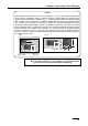
Coordinate conversion library
“viTrans6” is registered to
the Vision class in the
program bank. To convert
coordinates, add the library
“viTrans6” to the project. For
the method of addition, refer
to Chapter 5 “5.6.2 Program
Bank” in this manual.