
User Manual


8/17/2005 CavitronRF Combo - DFU Draft 08-01-05 Rev8doc
DRAFT
Page 7 of 18
• The Cavitron® RF™ Combination System is designed for a level surface. Be sure unit is stable and
resting on four feet.
• Placing unit in direct sunlight may discolor plastic housing.
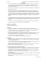
5.7 Power Cord/Power Connection
(Picture)
• Verify the main Power Control ON/OFF switch, located at the center front underside of the system, is
set to the OFF position before proceeding.
• Insert the detachable AC power cord into the power input on the back of the system.
• Insert the pronged plug into an approved AC wall outlet.
5.8 Water Supply Line Connection
(Picture)
• Grasp the Water Supply Line (blue hose) by the end closest to the water filter and insert it into the
water receptacle located toward the bottom center of the back panel until the hose cannot be pushed in
any further.
• Connect the free end of the water supply line to the office water supply line or a Cavitron® DualSelect™
Dispensing System. If your system’s water supply line is provided with a quick disconnect, connect the
quick disconnect to the dental office water supply line or a Cavitron® DualSelect™ Dispensing System.
• Inspect all connections to make certain there are no leaks.
• To remove the water line from the Cavitron® RF™ Combination System, turn off the dental office
water supply. Disconnect the water supply line from the dental office water supply. If a quick-
disconnect connector is attached to the end of the hose, relieve the water pressure by pressing the tip of
the connector in an appropriate container and allow water to drain. To remove hose from the system,
push on the outer ring of the systems water inlet and gently pull the water line out.
5.9 Air Supply Line Connection
(Picture)
• Grasp the Air Supply Line (black hose) into the air receptacle located at the lower left corner of the
back panel until the hose cannot be pushed in any further.
• Connect the free end of the air supply line to the dental office air supply or a Cavitron® Dual Select™
Dispensing System. If your system’s air supply line is provided with a quick disconnect, connect the
quick disconnect to the dental office air supply or a Cavitron® DualSelect™ Dispensing System.
• Inspect all connections to make certain there are no leaks.
• To remove the air supply line from the Cavitron® RF™ Combination System, turn off the dental
office air supply. Disconnect the air supply line from the dental office air supply, then push on outer
ring of the system’s air inlet and gently pull out air line.
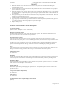
5.10 Footswitch Battery Replacement
(Picture)
• Turn footswitch over and using a Philips screwdriver, carefully remove battery cover screw and battery
cover.
• Remove used batteries and install two new “AA” batteries as shown. Discard used batteries in
accordance with local, state and regional regulations.
• Replace battery cover and screw and hand tighten with Philips screwdriver.
5.11 Footswitch Synchronization
Your Cavitron® RF™ System comes equipped with a footswitch which has remote operation capabilities.
To ensure that the particular footswitch sent with your Cavitron RF system works with the system base, a
unique address has been programmed into both the system base and the footswitch. If for any reason
address synchronization is required, your Cavitron RF System has been designed so that this can be
performed in the operatory environment. Perform the following steps to synchronize the footswitch with
the system base.
1. Turn the main Power Control switch located at the center front underside of the System to the OFF
position.
2. Install a new set of “AA” batteries into the footswitch. (See Section 5.8) Leave the battery cover of
the footswitch open so the red button switch is accessible.