
User Manual


8/17/2005 CavitronRF Combo - DFU Draft 08-01-05 Rev8doc
DRAFT
Page 8 of 18
3. Maintain a distance of no more that 10 feet between the system base and footswitch during the
synchronization process.
4. Turn the main Power Control switch to the ON position and wait for the Information Center graphics
(refer to Section 6.2) to light.
5. While all graphics are lit, press the Purge button, also located on the Information Center. The graphics
will begin to blink in a sequential pattern, representing the synchronization mode. This mode will last
5 to 6 seconds.
6. During this mode, press the red button located in the battery compartment of the footswitch. This will
complete the synchronization process.
7. Synchronization is successful when all graphics blink at the same time.
8. To verify proper communication, press the footswitch to the Boost position (footswitch fully pressed –
2
nd
position) and ensure the Boost graphic on system base lights.
9. Replace battery cover.
Section 6: Cavitron® RF™ Scaler Description
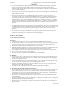
6.1 System Controls
(Picture of Unit / Handpiece / Cable / Footswitch)
Main Power ON/OFF Switch
ON/OFF Switch located at the center front underside of the system. The ON/OFF switch disconnects
power to all internal electrical circuits in the system base.
Ultrasonic Power Control
Turn knob to select ultrasonic power level for operation: clockwise increases system power, counter
clockwise decreases system power. For Air Polishing Procedures, the knob must be set past the Blue Zone.
The Blue Zone is an extended low-power range providing effective subgingival debridement and greater
patient comfort during definitive therapy. This zone cannot be used during air polishing procedures.
Rinse
Turn Ultrasonic Power Control knob fully counter clockwise until “click” is heard. Rinse mode is for use
during an ultrasonic scaling procedure when lavage is wanted without ultrasonic tip action.
Information Center
See Section 6.2.
Handpiece
Accepts all Cavitron® 30K™ Ultrasonic inserts and transmits power and lavage from the System to insert.
It also accepts the Cavitron® JET Air Polishing Insert which automatically selects air polishing mode.
Handpiece Holder
Securely holds the system’s Handpiece (with or without insert) when the system is not in use. Also holds
cable connector when handpiece is not installed.
Powder Fill Cap
Removable cap for filling and emptying the powder bowl. An adjustable pointer increases or decreases
powder flow rates.
Lavage Control (Flow Adjustment)
See Section 6.3
Foot Control
See Section 6.6
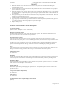
6.2 Information Center Graphic Displays and Control
(Picture)